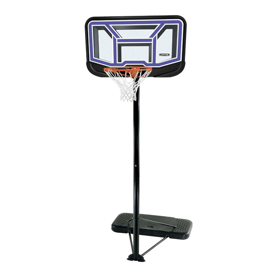
Lifetime 90114 Owner's Manual
Hide thumbs
Also See for 90114:
- Assembly instructions manual (36 pages) ,
- Assembly instructions manual (36 pages)

Related Manuals for Lifetime 90114


Summary of Contents for Lifetime 90114
- Page 1 MODEL N° 90114 OWNER’S MANUAL Keep this Product ID Number and use when contacting Customer Service:...
- Page 2 Maintaining your privacy is our long-standing policy at Lifetime. And you can rest as- sured that Lifetime will not sell or provide your personal data to other third parties, or allow them to use your personal data for their own purposes.
-
Page 3: Safety Instructions
SAFETY INSTRUCTIONS To ensure safety, do not attempt to assemble this product without reading and following all instructions carefully. Check the entire box and inside all packing materials for parts and/or additional instruction material. Before beginning assembly, identify and inventory all parts and hardware using the parts and hardware lists and identifi... - Page 4 TOOLS AND PARTS REQUIRED FOR THIS ASSEMBLY Phillips Screwdriver Sand (150 lb) Rubber Mallet *Two adults required to complete assembly*...
- Page 5 ASSEMBLY GUIDES Refer to the following areas throughout the instructions to assist in the assembly process: This area is located at the top, TOOLS AND HARDWARE REQUIRED FOR THIS PAGE left-hand corner of the page and indicates which tools and hardware are needed to on a page.
-
Page 6: Parts List
PARTS LIST Item Description Top Pole Middle Pole Bottom Pole Adjustment Knob Pole Plug Backboard Backboard Brace Base Upper Pole Brace Right Bottom Pole Brace Cross Tube Right Foot Wheel Warning Sticker (Applied to Middle Pole) HARDWARE LIST Item Description Streamline Hardware APG 5/16”... -
Page 7: Parts Identifier
PARTS IDENTIFIER Parts shown at 10% of Actual Size 43” ALH (x1) *Do not remove Top Pole from Middle Pole until instructed Top Pole 43” (x1) Middle Pole 43” ALE (x1) Bottom Pole 41” ALI (x2) Upper Pole Brace ALK (x1) Right Bottom Pole Brace (x1) BDB (x1) - Page 8 PARTS IDENTIFIER Parts shown at 10% of Actual Size ALX (x1) AKZ (x1) Parts shown at 5% of Actual Size (x1) Base (x1) Backboard Parts shown at 25%Actual Size (x1) (x1) (x1) Right Foot AMU (x2) Pole Plug Wheel (x1) Adjustment Knob...
-
Page 9: Hardware Identifier
HARDWARE IDENTIFIER Hardware shown at Actual Size APN (x1) 5/16” Flange (x2) 5/16” x 3 1/4” Hex Bolt APP (x1) 5/16” x 4” Carriage Bolt AAY (x1) AOT (x2) 1/2” Nylock 5/16” x 3 3/8” Hex Bolt Jam Nut 6 1/4” AZY (x2) (Not actual length) Base Plug... - Page 10 HARDWARE IDENTIFIER Hardware shown at Actual Size (x2) COC (x2) ABD (x15) 5/16” x 3/4” Hex Bolt 5/16” x 5/8” Screw for Plastic 5/16” Washer AOL (x2) AOM (x2) 5/16” x 3 1/4” Carriage Bolt 5/16” Cap Nut AOP (x2) AON (x2) ADS (x1) M6 x 35 Phillips Pan Head Screw...
-
Page 11: Hardware Required
POLE ASSEMBLY HARDWARE REQUIRED Hardware shown at Actual Size ADS (x1) 1/4” x 3/4” Screw AOL (x2) 5/16” x 3 1/4” Carriage Bolt AOM (x1) 5/16” Cap Nut PARTS REQUIRED Parts shown at 10% of Actual Size 43” ALH (x1) *Do not remove Top Pole from Middle Pole until instructed Top Pole 43”... - Page 12 TOOLS AND HARDWARE REQUIRED FOR THIS PAGE While the Top Pole (ALH) is still inside the , pull the plastic off the Top Pole. It may be necessary to loosen the Poles before pulling out the plastic. Sticker...
- Page 13 TOOLS AND HARDWARE REQUIRED FOR THIS PAGE (x2) AOL (x1) AOM (x1) Slide the Top Pole (ALH) far enough out of the so that it does not obstruct the holes at the bottom of the Middle Pole. Then attach the hardware indicated in the location shown. Do not overtighten the Cap Nut.
- Page 14 TOOLS AND HARDWARE REQUIRED FOR THIS PAGE AOL (x1) Position the Top Pole (ALH) at its lowest height and attach the to the Top Pole and with the hardware shown.
- Page 15 TOOLS AND HARDWARE REQUIRED FOR THIS PAGE ADS (x1) Align the hole in the with the slot in the Bottom Pole (ALE) and slide the Middle Pole over the Bottom Pole. Insert a 1/4” x 3/4” Screw (ADS) through the small hole in the Middle Pole into the slot in the Bottom Pole as shown.
- Page 16 TOOLS AND HARDWARE REQUIRED FOR THIS PAGE ATTENTION: THIS STEP CANNOT BE REVERSED! In order to seat the Poles, strike the end of the Bottom Pole (ALE) very hard fi ve to six times on a piece of scrap wood or cardboard. This must be done even if the covers the slot on the Bottom Pole before seating has occurred.
- Page 17 RIM & BACKBOARD TO POLE ASSEMBLY HARDWARE REQUIRED Hardware shown at Actual Size APO (x1) 5/16” x 4 1/2” Carriage Bolt APP (x1) 5/16” x 4” Carriage Bolt (x2) 5/16” x 3 1/4” Hex Bolt AAO (x5) COC (x2) APN (x1) 5/16”...
- Page 18 RIM & BACKBOARD TO POLE ASSEMBLY PARTS REQUIRED Parts shown at 10% of Actual Size ” ALX (x1) (x2) Backboard Brace Part shown at 5% of Actual Size (x1) Backboard TOOLS REQUIRED (x2) (x1)
- Page 19 TOOLS AND HARDWARE REQUIRED FOR THIS PAGE Insert Rim Brackets of the Rim (ALX) into the slots on the front of the Rim Brackets Rim Braces Note: The Rim Braces will remain outside of the Backboard slots as shown.
- Page 20 TOOLS AND HARDWARE REQUIRED FOR THIS PAGE HAVE ONE ADULT HOLD THE BACKBOARD AND RIM ASSEMBLY UNTIL THIS SECTION HAS BEEN COMPLETED Top Pole (ALH) with the holes in the Backboard as shown and place the Top Pole between the Rim Brackets. Rim Brackets...
- Page 21 TOOLS AND HARDWARE REQUIRED FOR THIS PAGE APO (x1) APP (x1) Insert the 5/16” x 4 1/2” Carriage Bolt (APO) through the Rim (ALX) in the hole indicated, and insert the Bolt into the upper hole on the and into the Top Pole (ALH). Also insert the 5/16” x 4” Carriage Bolt (APP) through the bottom hole in the Backboard and into the Top Pole.
- Page 22 TOOLS AND HARDWARE REQUIRED FOR THIS PAGE (x1) AAO (x1) APN (x1) ABD (x1) Attach the Rim (ALX) to the and Top Pole (ALH) by securing a with a onto the 5/16” x 4 1/2” Carriage Bolt (APO). Also secure a (APN) onto the 5/16”...
- Page 23 TOOLS AND HARDWARE REQUIRED FOR THIS PAGE (x2) (x2) AAO (x2) ABD (x4) Secure the Rim Brackets and Rim Braces to the Top Pole (ALH) with the hardware shown.
- Page 24 TOOLS AND HARDWARE REQUIRED FOR THIS PAGE 3/8” (x1) COC (x2) Secure a to the using the hardware shown. Do not overtighten the hardware.
- Page 25 TOOLS AND HARDWARE REQUIRED FOR THIS PAGE (x2) (x2) AAO (x2) ABD (x4) Attach the from Sec 2.7 to the Rim Brackets with the hardware shown. Repeat Sec 2.6 and 2.7 to attach the other Backboard Brace to the Backboard and Rim Brackets. Note: The hole in the Backboard Brace is slotted.
- Page 26 POLE TO BASE ASSEMBLY HARDWARE REQUIRED Hardware shown at Actual Size 6 1/4” (Not actual length) AOS (x1) AOR (x1) 1/2” x 6 1/4” Cap Screw 1/2” Washer AOT (x1) 5/16” x 3 3/8” Hex Bolt AAY (x1) 5 1/2” 1/2”...
- Page 27 POLE TO BASE ASSEMBLY PARTS REQUIRED Parts shown at 10% of Actual Size 41” ALI (x2) Upper Pole Brace ALK (x1) Right Bottom Pole Brace (x1) BDB (x1) Cross Tube Parts shown at 25% of Actual Size (x1) (x1) (x1) Right Foot AMU (x2) Pole Plug...
- Page 28 TOOLS AND HARDWARE REQUIRED FOR THIS PAGE (x1) AOP (x2) AON (x2) Attach the Cross Tube (BDB) to the ALK) with the hardware shown. Do not overtighten the Cap Nut. Fit the Bottom Pole Brace Assembly within the recesses on the underside of the as shown.
- Page 29 TOOLS AND HARDWARE REQUIRED FOR THIS PAGE (x2) AOO (x2) ABD (x4) AAO (x2) Attach the Upper Pole Braces (ALI) to the and the Bottom Pole Brace Assembly with the hardware shown. Underside View of Base...
- Page 30 TOOLS AND HARDWARE REQUIRED FOR THIS PAGE 6 1/4” (Not actual length) AOS (x1) AAY (x1) (x1) AOR (x1) (Not actual size) CAUTION: HAVE ONE ADULT HOLD THE POLE UNTIL THE Insert the into the Bottom Pole (ALE) in the orientation shown.
- Page 31 TOOLS AND HARDWARE REQUIRED FOR THIS PAGE (x2) AOT (x1) AOM (x1) ABD (x2) Attach the Upper Pole Braces (ALI) to the Bottom Pole (ALE) with the hardware shown. Do not overtighten the Cap Nut.
- Page 32 TOOLS AND HARDWARE REQUIRED FOR THIS PAGE 5 1/2” (Not actual length) (x2) Insert the into each as shown. Place the Axle and Wheel Assemblies underneath the indentations at the back of the . Then step on the Base to snap them in place.
- Page 33 HARDWARE REQUIRED Hardware shown at Actual Size AZY (x2) Base Plug PARTS REQUIRED Part shown at 10% of Actual Size AKZ (x1) TOOLS REQUIRED Sand (150 lb)
- Page 34 TOOLS AND HARDWARE REQUIRED FOR THIS PAGE AZY (x2) (150 lb) (150 lb of sand required) a. Insert a Base Plug (AZY) into the in the hole closest to the Pole. b. Using a funnel, fi ll the Base with sand through the hole furthest from the Pole until the sand is just below the hole.
- Page 35 TOOLS AND HARDWARE REQUIRED FOR THIS PAGE AZY (x2) a. Insert a Base Plug (AZY) into the in the hole closest to the Pole. b. Fill the Base with cold water through the hole furthest from the Pole until the water is just below the hole. c.
- Page 36 TOOLS AND HARDWARE REQUIRED FOR THIS PAGE Attach Net (AKZ) to the Rim (ALX). Note: If a replacement Net is needed, please call our Customer Service Department. Our Nets are shorter than average to reduce the risk of entanglement.
-
Page 37: Moving The System
OPERATION OF HEIGHT ADJUSTMENT SYSTEM The basketball system may be adjusted from 7 1/2 feet to 10 feet. a. Using at least two adults, tip the system backward and rest the Pole on a table. Do not scrape the powder coating off the Pole while adjusting the system, or you could void the product warranty and cause rusting. - Page 38 POLE CARE AND SYSTEM MAINTENANCE The life of your basketball system depends on many variables. The climate, exposure to corrosives such as salt, pesticides, or herbicides, and excessive use or misuse can all contribute to Pole failure, which may cause property damage or personal injury. Check your basketball system frequently for loose hardware, excessive wear, and signs of corrosion.
- Page 39 NOTES...
- Page 40 NOTES...
- Page 41 NOTES...
- Page 42 ® ENHANCE YOUR LIFETIME PURCHASE BY ADDING ACCESSORIES OR OTHER GREAT PRODUCTS: To purchase accessories or other Lifetime Products, visit us at: www.lifetime.com Or call: 1-800-424-3865...
- Page 43 N’accrochez rien au manche, brazos de elevación, ya que esto puede dañar el sistema y anular à l’anneau, au panneau ni aux leviers sous peine d’endommager la garantía. l’équipement et d’annuler la garantie. www.lifetime.com #1007960 1/12/2006...
-
Page 44: Warranty Information
This warranty gives you specifi c legal rights, and you may also have other rights which vary from state to state. **Call or visit our Web site for Saturday hours** Please include your dated sales receipt and photographs of damaged parts. www.lifetime.com...
Need help?
Do you have a question about the 90114 and is the answer not in the manual?
Questions and answers