Table of Contents
Advertisement
Quick Links
CAUTION: B efore p utting relays into serv ice, re
mov e all blocking which may hav e been inserted for
the purpose of s e curing the parts during s hipment,
make sur e that all mov i ng parts operate fre elY, in
spe c t the contacts to see that they ar e clean an d
close properly, and operate the relay to che ck the
setting s and electrical connections.
APPLICATION
The type KP re lay is a three phase hig h spe ed
voltag e and phase sequenc e relay.
Th is relay can be used as e ither an underv oltag e
or ov erv oltage fault detector. In addition, it can also
be use d to check phase s e qu e nce of a thr e e .P hase
v o ltage.
C ONSTRUC TION AND OP ERATION
an
The type KP relay consists of a hig h speed
cylinder unit with
adjustable spring and an in
dicating cont actor switch when re quired.
Voltage Unit
The voltag e unit is a product induction cylinder
typ e unit.
Mechanically,
the
overcurrent u nit is composed
ofthree basi c components: a die-cast aluminum fram e
and electromag net, a moving e lement assembl y , and
a molded bridg e .
The frame serv e s as the mounting structure for
the mag n etic core. The Irag netic core which houses
the lower pin bearing is .o e c ured to the frame by a
spring and snap ring . The b e ar ing can be replaced,
if nece ssary, without hav ing to remov e the m ag n etic
core from the frame .
The el ectromag net has two pairs of coils. The
coils of each p air are mounted diametrically opposite
one another. In addition, there ar e two locating pins.
The locating pi ns are used to accurately position the
lower pin b e aring , which is mounted on t h e frame,
with r e spe ct to the
upper pin bearing,
SUPERSEDES LL. 41-222.4
*Denotes change from superseded issue.
INSTALLATION
I N S T R U C T I O N S
TYPE KP THREE PHASE VOLTAGE
AND PHASE SEQUENCE RELAY
which is
Westinghouse
•
OPERATION
threaded
i nto
the
bridg e .
permanently
se cured t o the frame
s epar at e d from the frame.
The
mov i ng
el ement
spiral
spring,
contact
aluminum cylinder assembled to a molded hub which
holds the shaft. The shaft ha s remov able top and
bottom j e wel bearing s . The shaft rides between the
bottom p in b e ar ing and the upper pin b earing with the
cylinder rot ating in an air g ap formed by the elec
tromagnet and the mag netic core .
The bridg e is secured to the electromag net and
frame by two mounting scre ws. In addition to holding
the upper pin bearing, the bridg e is used for mounting
the
adj ustable
stationary
stationary contact hous ing i s held in position by a
spring type clamp. The spring adj uster is located o n
the underside of the bridg e and is attac he d t o the
mov ing contact arm by a spiral spring . The spring
adj uster
is also held
clamp .
With the contact s closed, the ele ctrical conn e c
tion is made throug h the stationary contact housing
clamp,
to the mov i ng
spring o ut to the spr ing adj uster clamp .
The voltag e at which the contacts e ither pickup
or dropout can be v aried by me ans of moving the
spring adjuster.
Indicating Contactor Switch Unit (ICS)
Th e indicating contactor switch is a small d- e
operated clapp er type dev ice. A mag netic armature,
to which l eaf- spring mounted contacts are attac he d ,
is attracted t o t h e mag netic core upon e nerg i zation
of the switch. When the s witch close s, the mov i ng
contacts bridg e two stationary contacts, completing
the trip circuit. Also during this operation two fing ers
on the armature deflect a spr i ng located on t he front
of the switch, which allows the operation indicator
target to dr op. The targ et is re s et from the outside of
the case by a push rod located at t he bottom of
the c ov er .
EFF ECTIVE OCTOBER 1969
LL. 41-222.4A
•
MAINTENANCE
The
electromag net
and cannot b e
assembly
consists
of a
c arrying
member,
a nd
contact
housing .
The
in plac e by a spring typ e
contact, throug h the
spiral
i s
a n
Advertisement
Table of Contents

Subscribe to Our Youtube Channel
Related Manuals for Westinghouse KP


Summary of Contents for Westinghouse KP
- Page 1 The type KP re lay is a three phase hig h spe ed tromagnet and the mag netic core .
- Page 2 . However, if a nother Th e mov ing c o ntact a s sembly in th e KP volta ge volta ge s ett ing is requ ired, the n the follo wing pro...
- Page 3 TYPE KP THREE PHASE VOLTAGE AND PHASE SEQUENCE RELAY ot her t ha n t ho s e cov ered under " Setting s ," should should not be used unle s s it is appa rent t hat the be req uired.
- Page 6 TYPE KP THREE PHASE VOL TAGE AND PHASE SEQUENCE RELAY CONTACT MMIIIL.LI!;EOONI[)$ TIME TO CLOSE LOW VOL 00 g� < << << �:iii 0< ..-i o ,..,..,..,..,..,..
- Page 7 I.L. 41-222.4A TYPE KP THREE PH ASE VOLTAGE AND PHASE SEQUENCE RELAY 1, 2i 3 D. C. TRIP SUS PHASE ROTATION POS. NEG. 47 -1 NEG. POS. DEVICE NUMBER CHART REVERSE PHASE RELAY, TYPE KP 11- 7 -ll- 47-2 1, 2 & 3...
- Page 8 TYPE KP T HREE PHASE VOLTAGE AND PHASE SEQUENCE RELAY I& I SI0-32 SClEW • TocmtED LOCDASHER PAII E L THIN fAII E LS SPACEIS FOit -18 SClEW THICK miD) .190-32 SCREW DIA.I 0 ltOUS '"i" Ott CUT OUT TERNIMAL AND...
-
Page 9: Installation
The typ� KP re lay is a three phase hig h speed t ro m a g net and t he mag net ic co re . - Page 10 . Loo king at th e front v ie w and F actor y calibrat ion is 7 0 volt s . fro m th e top of th e KP r elay, the 3 0 volt adju stm e nt Th e K P Volt age...
- Page 11 TYPE KP THREE PH AS E VOLTAGE AND PHASE SEQUENCE RELAY ot her t han tho s e cov ered und e r "S ett ings," should should not be used unle s s it is apparent that th e be required.
-
Page 12: Renewal Parts
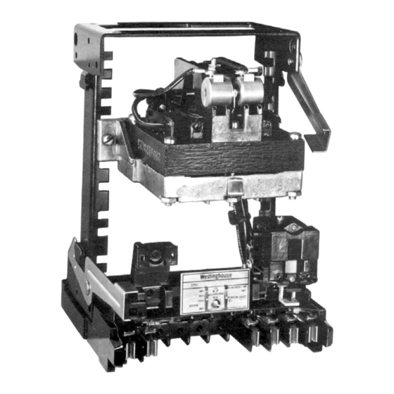
T o decrease the pickup current bend t he t h e c omplet e nameplate dat a. springs in t o w ard the c ov e r. F ig. P h otograph- Type KP Re lay without case. - Page 14 MOUMTIMG DETAILS (FUIO' V IEW) 57-D-7901 Fig. O u t line ancl drilling p lan for the T ype KP V o ltage R e lay in the type F T21 case. WESTIN GHOUSE ELECTRIC CORPORATION U.S.A. N EWAR K , N.
- Page 15 Westinghouse I.L. 41-222.2G • • INSTALLATION OPERATION MAINTENANCE I N S T R U C T I O N S TYPE CP REVERSE PHASE RELAY C A U T ION Before putting relays into servic e , remove conn ected...
- Page 17 TY P ECP RELAY INTERNAL SCHEiilATIC SCHEMATIC INTERNAL LOW VOLTAiiE PKASE A P'KASE A RIGII T LEilCOI L lllll lt T LEW COIL PliASi PHASE CEIITEI POLE COIL CUTER POLE COIL PKASE C LEFT LEG COIL IIWICATIII6 CDIII T ACTOI S.ITCtl ll£0 MAMDLE TEST SWITCH...
- Page 18 high vol tage contact sup erv i s e s supply breaker INTERNAL cl osing, it must be set lower than nor mal v oltag e . sotOIATJC F or exampl e, set t h e high-v ol tage contact a t 90% and the low-v oltage contact at 80% of rated v oltage.
- Page 21 I . L . 4 1 - 2 2 2 . 2 G TYPE CP RELAY I NTERNAL SCHEMAT I C INTERNAL SCHEMATIC PHASE A R I GH T LEJ C O I L rt l litl �OLTAIJ£ LOW YOLTA.JE LO'i VOLTAGE A-C �OLTAGE SWIWI...
- Page 22 . 563 ( 14.30) • 25° DIA, 4 HOLE S FOR 16·351 . 1 90-32 MTG. SCREWS (74.63) ( 1 6 1 .93) PAN E L CUTOU T D R I L L I N G FOR SEM I - F LUSH M T G . .
- Page 23 Westinghouse 1 . L . 4 1 - 2 2 2 . 2 B • • INSTA L LATION OPERATION MAINTENANCE I N S T R U C T I O N S TYPE CP REVERSE PHASE RELAY C A U T ION...
- Page 24 TYPE CP RELAY SCALE PLATE LOW VOLTAGE CONTACT MOVING CONTACT Fig. Type CP Relay Witho ut Case. LOW VOLTAJE � I G� VOLT AilE- I CS P�ASE A IND I CATING R l o�T LE3 CO I L CONTACTOR SWI TCk - PMASE I•DICATIN<l �...
- Page 25 INTERNAL SCHEMATIC INTERNAL SCHEMATIC LOW YOLTA!lE PHA$E A PHASE � II:IQKT LEi COIL R I WI T LEa COIL PliASE B PltASE S iiiQH YOLT.\IIE COlTER POLE COIL CEJITEJ POLE COIL PHASE C -LEFT LEG COIL REO HANDLE TEST SWITCH TEIMilAL.
- Page 27 TYP E CP RELAY -- -- -- -- -- -- -- -- -- -- -- -- -- -- -- -- -- -- -- -- -- -- -- -- -- -- -- --�'·�L� -�41�·2� 2�2-�28 I t t ��tJ =:t: 1 ' t TYPICAL OVERVOLTAGE CURV ES TIME...
- Page 30 PA N E L CUTOUT DR\L\JNG F"OR. SEMI-FL\Jf>'-' MTG • . 1 9 0-3" SCREW � DIA.\-\OLE SPAC.ER FOR < PA.NEL� THICK PA.NE:L LISE. ( F'OR .2 - 19 ST UD\ . 1 9 0 ·32. �CREW TERMI�AL J>.. N D PANEL DR \ L L I NG 01<...
-
Page 31: Installation Instructions
I . L. 41 -222.2A • • INSTALLATION OPERATION MAINTEN A N CE I N S T R U C T I O N S TYPE CP REVERSE PHASE RELAY C A U T I 0 N Before putting relays into servic e , remove with respect to each other since they are induc ed all blocking which may have been ins ert�d for the out-of-pha se voltag es. - Page 33 TYPE CP RELAY INTERNAL SCHEMATIC INTERNAL SCHEMATIC PIAIE A P'I6ASE A l l!iiiT LEii COIL R l llM T LEQ COIL IUitl POLE PWE I PiiASE B VOLUiiE CUTER l"'LE COIL CEITEI COIL. II Iii 'IOLTAif - PIIAS( C LEFT UQ COIL I IU:I I CATIIIG COIIU.CTOI SIII I TC"...
- Page 34 A c c ep t a n c e C he ck following check is recommended to insure INTERNAL SCHEMATIC that the rel ay is in proper working order: CP Unit Contacts - Set the left-hand adj ustable co ntact LO'i VOLTAGE- - in the center of the scale and adj ust the voltage PHASE A...
- Page 35 TYPECP RELAY · RELAY - TYPE TYPICAL UNOERVOLTAGE TYPICAL OVERVOLTAGE TIME CURVES 1 10 -- H IGH VOLTAGE CONTACTS -- HIGH VOLTAGE CONTACTS SET AT VOLTS SET AT VOLTS " - - - HIGH VOLTAGE CONTACTS SET AT VOLTS <I> "...
- Page 36 t:>l� 4- H OLES FOR. "f-, 190-3Z M'TGr. SCREW� CUTO U T F"CR. SEMI-FLU&" MTGr PANEL t DRILLII'�G • . 1 9 0-3 Z. SCREW SPAC.S:R FOR THI"' P..._ N E\...� \8 'SC R.f:W IE> � - ( FOR THICK I<D ( F"OR 'Tio\ ICI<.
-
Page 37: Installation
Westinghouse 1 . L . 4 1 - 2 2 2 . 2 B • • INSTALLATION OPERATION MAINTENANCE I N S T R U C T I O N S TYPE CP REVERSE PHASE RELAY Before putting relays into servic e , remove... - Page 39 INTERNAL SCHEMATIC INTERNAL SCHEMATIC LOW WOLTA1U PHASE A PHASE A II: IGitT LEG COIL R I GHT LEQ COIL PWE i PIUSE B Iii� VOLTAGE ---- - c EMTEII POLE COIL CEIITER POLE COIL KIQH YOLTAGE - PKASE C PHASE C LEFT LEil COIL LEFT LEG COIL INDICATING...
- Page 40 ation of this relay have been made at the factory. Upon receipt of the rel ay , no adjustments, other INTERNAL SCHEMATIC than those covered under "Settings " , should b e required. A c cept a n ce C heck The following check is recommended to insure LOW VtX.TAGE that the relay is in proper working order:...
- Page 41 TYP E CP RELAY---------------------------------------------------- ----� � - � L� - � 41 � -2 � 2� 2 -� RELAY - TYPE RELAY - T Y P E TYPICAL UNDERVOLTAGE T Y PICAL OVERVOLTAGE TIME CURVES TIME CURVES 1 10 -- HIGH VOLTAGE CONTACTS -- H IGH VOLTAGE CONTACTS SET AT VOLTS...
- Page 42 . . ct/ ( ri'OiiriTE w ) CP' II£LAY S T OPa -· r.;:�·=: T IICI O TINEt STOf' TIWER STOP'S IIEUY TO TIMER WHEII AUX. STOP TINO STAITI Ml CONTACT OPENS T I MEI TO TIMER TIM£11 STARTS •s• STAll •nc.11 •s•...
- Page 44 �--- ; I 'DIA.. . 4- HOL E 'S SCROWS 90->2 M�-- ,... , \0 � " PA N E L CUTOUT DR\L\JNG F"OR SEMI-FLUf>\-4 MTG • . 1 9 0-3Z SCREW 16 DIA.. .'HOLE F CR P..._ N EL� �...
- Page 45 Westinghouse 1 . L. 4 1 - 2 2 2 . 2 8 • • INSTALLATION OPERATION MAINTENANCE I N S T R U C T I O N S TYPE CP REVERSE PHASE RELAY C A U T I O N...
- Page 46 TYP E CP R ELAY SCALE PLATE LOW VOLTAGE IDGHVOLTAGE POINTER CONTACT MOVING CONTACT Type CP Relay Without Case, LOW VOLTAJE P�ASE A R I GHT LEo CO I L P�ASE CENTER POLE CO I L PHASE C LEFT LEG C O I L TERMINAL NOTE: CONTACT...
- Page 47 INTERNAL SCHEMATIC LOW YOLTAiiE PriASE A PHASE A 11.1\iHT LEG COIL ____ _.- R I GHT Lfil COIL PHASE PHASE B __..- - CUTER POLE COIL COlTER POLE COIL HIGK VOLTAGE PHASE C PHASE C LEFT I.EG COIL - LEFT LEG C O I L LOW YOLTiQE ---- -- - -- II.ED HAHDLE RED IIAIIDLE...
- Page 48 ation of this relay have been made at the factory. Upon receipt of the rel ay , no adjustments, other INT£RNAL SCHEMATIC than those covered und er "Setting s " , should b e required. A c c ep t a n c e C he ck following check is recommended to insure LOW IIOLTAGE that the relay is in proper working order:...
- Page 49 t: t � �0 �0 VOLTAGE IN PERCENT VOLTAGE IN PERCENT HIGH VOLTAGE CONTACT SETTING LOW VOLTAGE CONTACT SETTING Curve Curve 471071 471072 Fig. 7. Typical Undervoltage Time Curves lor the Type CP Fig. 6. Typical Overvoltage Time Curves lor the Type CP R elay.
- Page 50 R£L.AY (FIOiifYTEW ) } TO TI NE I{ T UIU ITOPI .. "" � :: � ' =. •s• CLUIS TO Tn•U{TI NO JT. U TI S TAll SWI T tt l 184Al99 184Al95 Fig. 8. D iagram of Test Connection for checking the Fig.
- Page 51 D . C . TR I P IWS PO S . IIEII. D E V I C E N U M B E R CHAR T �7 - R E V E R S E PHA S E R E LA Y , TYPE CP �7- 1 ) - &...
- Page 52 PANEL CUTOUT F"OR. SEMI-FL\Jf>'"' MIG t DRILUI'{G • . 1 9 0-3Z. �RE.W TERM I "l�L �NO M O UNT I NG- DE.T�IL.5> N\ � N S I O N5. N O T E : A LL D l I N C H E S., 57-D-7900 Fig.
- Page 53 LL. 4 1 -222 .2 • • OPERATION MAINTENANCE INSTALLATION I N S T R U C T I O N S TYPE CP REVERSE PHASE RELAY C A U T I O N Before putting relays into servic e , remove with respect to each other since they are induc ed all blocking which may have been ins ert�d for the out-of-pha se voltages.
- Page 55 �- TYPE CP RELAY INTERNAL SCHEMATIC L OW 'i'OllAGE lliiiiH PIIA$E A PKASE A LEG COIL R I GKT LEG COIL PHASE PliASE S KliH 'i'OLTAIIE It II l ii __...- - CEIITEII POLE COIL. CEJHER POLE COIL VOLTAGE -- LOll VOLTAGE ------- IIOTE: COMTACT IS I ll Tit£...
- Page 56 ept a n e C he following check is recommended to insure that the relay is in proper working order: CP Unit Contacts - Set the left-hand adjustable contact LOW 'IOlTAGE in the center of the scale and adjust the voltage PHASE A R h iKT LEG COIL until the moving contact just makes.
- Page 57 :TYPE CP RELAY RELAY - TYPE RELAY - TYPE TYPICAL OVERVOLTAGE TYPICAL UNDERVOLTAGE TIME CURVES TIME CURVES -- H IGH VOLTAGE CONTACTS -- HIGH VOLTAGE CONTACTS SET AT VOLTS SET AT VOLTS - - - HIGH VOLTAGE CONTACTS HIGH VOLTAGE CONTACTS SET AT VOLTS SET AT...
- Page 58 (nX:l�'itJ) CP RELAY (FIOiiri il W ) � ��a: } TO TI N U{ T U U ITOI'S .. S T OP •s• TO TU O {TI NEI IT &ITI I T CM CLOII. I STAll 3 PHASE CYCLE VOLT s�""L' 184Al99 184Al95 Fig, 8.
- Page 59 TYP E CP RELAY Tll i P iij$ PO S . PH A SE iO TAT I O• 1 , 2 , 3 MEa. D E V I C E N U M B E R CHART �7 - R E V E R S E PHA S E R E LAY , T Y P E CP &...
-
Page 61: Construction And Operat I On
I. L. 4 1 - 222. 1 • • INSTALLATION OPERATION MAINTENANCE I N S T R U C T I O N S TYPE CP REVERSE PHASE RELAY Before putting relays into servi ce , re form a double throw arran gement . It i s fastened on C A U T I O N move all blocking which may have tleen inserted for... - Page 62 TYPE CP RELA Y INTERtfAL SCHEMATIC INTERNAL SCNEMAT I C PH.UE .l PHASE A LOWER POLE COIL lOWEI POlE COIL PHASE PHAIE LOWER POlE COIL llllt 'I OI. TA&E H I GII VOLTAGE-- LOWEll POLE COIL LOW VOLTAGE VOl TAlE PHASE PHASE C UPPEI POLE COILS...
- Page 63 .4 1 · 222 . 1 I. L TYPE CP RELAY • >II , .. "' ·- � •( � · " <( " � 0 4.0 > w •. 0 .. "' ..P.� ("" . ( ::_li_QP-cJ" _ .(ONT.A.CT VflLTAG:r- &FTTING VOLT.I..
-
Page 64: Adj Ustments And Mai Ntenance
TYPE C P RELAY CP IELAY (FIIi iTYib ) (FJtl;tl�) INEM T lW ER STOPS } TO TINEII g.;:� Y O � �= STOP •s• } TO T !MER {TINER STAaTS WIIU START SWITCH CLOSES l83A328 l83A329 Fig. 5. D i agram of Test Connections for Checking the Fig. -
Page 65: E Nergy Requi Rements
TYPE CP RELAY IIOTATIOII PHASE 1 , 2 , 3 S LOT POS. ICE IUIMIEI CIWIT .l'::l 0 -3 2 sc. �7 �! REVERSE PliASE RELAY, TYPE CP ·· EXTERNAL RESISTORS 4 7 - 1 �7-2 4 7 - 3 02 - - PHASE 1,2 COILS RESPECTIVELY POWER C I R CU I T BREAKER... - Page 66 DI A- - 4- HoLE.S FOR + . 190·3'2. MTC:r. <:>CREW$ Pt>.NEL CUTOUT I.ATG ORILLI � G I'"OR SE'M I - F LU5\-I • 1 � 0 -32. SCREW • SPACER FOR T�IN PAt-tl:: \. .<;. � -19SCRE.W (FO� "T\-\IC\o<.. 16- 18 �EL STUD)
- Page 68 W E S T I N G H O U S E E L E C T R I C� C O R P O R A T I O N M E T E R D I V I S I O N N E W A R K , N .
- Page 69 � J I . L . 4 1 -222 . 1 A • • I N S T A L L A T I O N O P E R A T I O N M A I N T E N A N C E I N S T R U C T I O N S TYPE CP REVERSE PHASE RELAY Before...
- Page 70 T Y P E CP R ELAY INTERNAL SCHEMAT IC INT£1ttt A L SCMENAT I C PHASE A PHASE A LOWER POLE COIL LOWEll POLE COIL PHASE PHASE lllll wot.TAG£ LOWER POLE COIL HIGH vou.u,£-- LOW£11 POLE COIL LOW VOLTAQ£ VOL TAlE PHASE C PHASE C...
- Page 71 T Y P E CP RE LAY 4 1 -222 . 1 A I . L . "' 41> .. . � � "' <.( t � � <( "' f · <( > � 0 3. � 3. "' 2 �...
- Page 72 T Y P E CP R E LAY CP RELA Y (FMiin! EW) HNEI STOPS IHEM TO TINER TINER STOPS � �;�� Y O �;: STOP TINER IKEit AUX. STOP IEU Y Cott T ACT OPEJIS •s• TO TIM£R TIMER STARTS TO T IMER TINEII STARTS Wlii U SIAIIT INEII SWITCH...
- Page 73 TYPE CP R E LAY f'KASE I!.DTATIOM 1,2.,3 ------ -1 lliE'J. � � · �:.l. i . - - - S LOT POS. .1'::1 0 - 3 2 sc. D E � I C t: IIUMdER CKART � RE�ERSE PttASE RELAY, TYPE CP L ) - EXTERNAl RESISTORS -.7-l.
- Page 76 - - � � -�- - -- --------- - - -� -� ---� W E S T I N G H O U S E E L E C T R I C C O R P O R A T I O N M E T E R D I V I S I O N N E W A R K , N .
- Page 77 L. 41 - 22 2 • • INSTALLATION OPERATION MAINTENANCE I N S T R U C T I O N S TYPE CP REVERSE PHASE RELAY CAUTION Be fore put t ing rAlays into service , induct i on d i s c i �...
- Page 78 TYPE CP RELAY � �'f,k' T ,:,]!� � 1-liG.\' o �§;"- VOL T AGE =�� � � ����ii!L OCK CONTACTS RELAYS. I<ELAYS. li!lm<lN INDICATOI< C ---t- - UPPER POLE COILS PI<A1i>E LOWER i'OLE COIL PHASE RE.AR REAR VIEW VIEW VIEW) CONTACT t-IOTE : MOVING.
- Page 79 TYPE CP RELAY (.OVI!ifir O�llil"'TE:O ;oWITCM WHII!.H u�a.O P H RSE C REAR V/�W VPPER P tJLE COILS T EST SWITCH lf AIYO t./HEIY THE V oLT Is Low 0 fl 7iiE P HR.JE REVERSEO. t<oNr 1/oJ.. T ITfiE T HE PfiRSE Nor<: COt!T RCT /S I ff THE LEFT Po.$/T/0/Y Nor£...
- Page 80 TYPE CP RELAY mat e ly 0 . 25 ohm, and i s suitable for a l l t rip t ou ch on e ither side of the moving cont act . the t rip curren t s above 2 . 25 ampe re s d - e . Thi s is done by l o o sening...
- Page 81 TYPE CP RELAY up . Thi s can be mo st conven ient ly done by f a c t o ry . Howe ve r , int e r change able turning the relay up - s ide -down . S c rew up the part s can be...
- Page 82 TYPE CP RELAY Curve 282257 0 '7. � . AT � � •t � "' � c· ..� � � o :r TACTS ..<'t � � � � � � � � Curve 282258 VOLTA�!. � VOL TA't .SUooEN(V'' FRb'M"...
- Page 83 TYPE CP RELA Y -- -- -- -- -- -- -- -- -- -- -- -- -- -- -- -- -- -- -- -- -- -- --�'-�L� 4�1-2�2 2 C'K'T B'K'R 2 sc. · REAR VIEW TOP TERMINAL NO. FOR ..
- Page 85 Westinghouse I . L. 41 -222.2G • • I N S T A L L A TI O N O P E R A T I O N M A I N TEN A N CE I N S T R U C T I O N S...
- Page 87 TYP E CP R ELAY LOI VOLTA�£ PHASE A PI&ASE I aNT LEQ COIL 11:1\IIIT LEG COIL PKASl II Uill PWE I CEITU: POLE COIL N l iH VOlTAIK CEMTU POLE 'i'OL T Aif PMASE C PKASE C - LEFT LEU COIL -LEFT LEil COIL IIIDICATI116 CotiTAtTOl SW I TCII...
- Page 88 high voltage contact supervi ses supply breaker closing, ilt must be set lower than normal voltage. For example, set the high-voltage contact at the low-voltage contact at of rated voltage. The .., ... --+--- -1 high and low voltage contacts must be sufficiently separated to allow for a minimum contact gap of about 0 .
- Page 90 C, R£U.Y (FII&rl���) (fniifVI EW) ��!�'=- TUIEI{ TU IE I ST OP S -· ST" W1E1 •s• CLOII: S TINEa {TUG SUIT$ STAll S.ITeM 2i • ..��SE VOLT �I"I"LY SUB 2 SUB 2 184Al95 184Al99 Fig. 9. f)iagram of Test Connection for checking the Fig.
- Page 91 I . L . 4 1 - 2 2 2. 2 G TYP E CP RELAY INTERNAL SCHEMAT I C INTERNAL SCHEMATIC PHASE A R I GtH LEU C O I L ri I ..IIi IIOLTA�E PHASE a LOW VOLTAGE CEI'HER POLE C O I L LOW VOLTAGE PtiASE C...
- Page 92 i�� . 563 ( 14.30) DIA. HOLES FOR . 1 90-32 M'ro. SCREWS 7. 250 ( 1 8 4.15) (74 .63 ) 6.375 ( 1 6 1 . 93) PAN E L CUTO U T DRI L LI N G FOR SEM I - FLUSH MTG .
- Page 93 Westi nghouse I. L 41 -222.2G • • I N S T A L L A TI O N O PE R A T I O N M A I N T E N A N C E I N S T R U C T I O N S TYPE CP REVERSE PHASE RELAY C A U T I O N Before putting relays into servic e , remove...
- Page 95 TYP E CP R ELAY INTERNAL SCHEIII A TIC -t l _ _ _ _ - :�:�� � LOW 'f'OLTA\lE - -- - PKASE A ___. - RI()HT LEil COI L Eil COIL 1 1cs PKASE 8 ll l llH PrtASE 8 - CEIITER POLE COIL IIIQII YOLTA1:1E...
- Page 96 high voltage contact supervi s e s supply break e r INTERNAL SCHDIATJC closing, it m u s t b e s e t lower than normal voltag e . F o r examp l e , set t h e high-voltage contact at 9 0 % and the low-voltage contact at 8 0% of rated voltage .
- Page 99 4 1 · 2 2 2 . 2 G TYPE CP R ELAY I . L . INTERNAL SCHEMATIC I NTERNAL SCHEMAT I C f'HASE A il: I Gri T LEJ CO I L 1 ..!11 �OLT Ai.i£ � PHAS E LOW �OLU\i£...
- Page 100 . 563 ( 14 . 3 0 ) ' 2 S O D I A . 4 HOLES F OR (G.3 S ) , 1 90-32 MTG. SCREWS ( 1 8 4.15) 7. 250 ( 1 6 1 .93) PAN E L CUTO U T DRI L LI N G FOR SEM I - F LU S H M T G .
Need help?
Do you have a question about the KP and is the answer not in the manual?
Questions and answers