Advertisement
Quick Links
B efore putting relays into servi c e , remove
C A U T I O N
all blocking w hich may have been ins erted for the
purp o s e of s ecuring the parts during shipment, make
sure that all moving parts op erate freely , inspect the
contacts to s e e that they are clean and close prop er
ly, and op erate the relay to check the settings and
el ectri cal connectio n s .
A P P L I C A T I O N
The type KA-4 relay is an auxiliary relay u sed
in a distan c e c arrier relaying scheme to block or
prevent in stantaneous tripping for faults e xternal to
th e line s ection to which it is appli ed , and to permit
instantan eous
simultan e o u s
faults . The relay i s arran ged to respond to indica
tions of fault power and direction provid ed by phase
and
ground relay s , thereby controllin g the trans
mis sion of th e carrier sign als .
C O N S T RU C T I O N A N D O P E R A T I O N
The Type KA-4 relay c onsists of tw o auxiliary
unit s , receiver and alarm unit s , phase fault c arrier
operation
indicator
and c arrier squelch relay . In
addition , the type KA-4 rela y c ontains a high speed
overcurrent unit
used
for ground fault s . The c onstruction and operation
of the relay units are de scribed below . Complete
details of the operation of this relay in the distance
c arrier re laying scheme is described in I . L . 4 1 -9 1 1 .
Overc urrent U n i t
*
The ove rcurrent unit consists o f a trans form er,
current limiting reactor , and a product induction cyl
inder t ype unit. The time phase relationship o f the
t wo air gap fluxes n e c e s s ary f or th e development o f
t orque of the cylinder unit is achieved by m eans of
a capacitor connected in s eries with o n e p air o f
pole windin g s .
Mechanically , the cylinder unit i s composed of
three basic compon ents:
and electromagnet, a moving element assembly , and
a molded brid g e .
SUP ERSE DES I . L . 41-923.4G
*Denotes changes from superseded 1ssue.
INSTRUCTIONS
I N STAL LATI O N
TYPE KA-4 CARRI ER AUXILIARY R ELAY
tripping
for
internal
to
start carrier transmission
a die-c ast aluminum frame
Westinghouse
•
O P E RAT I O N
The frame s erves as the mounting structure for
the magnetic core.
The m agnetic core which hous e s
t h e lower p i n b earing i s s ecured t o t h e frame b y a
spring and snap ring.
if necessary, without having to remove the m agnetic
core from the frame .
T h e electromagnet h a s two p airs of coils.
coils o f each p air are mounted diametrically oppo site
one another. I n additi o n , there are two l ocating pins.
The l o c ating pins are used to accurately po sitio n the
lower pin bearing, which is mounted o n the frame,
with resp ect to the upper pin b e aring, which is
threaded
into the
bridge.
p ermanently
secured t o t h e frame and cannot b e
separated from t h e frame .
The
movin g
elem ent
spiral
spring,
contact
aluminum cylinder assembled to a molded hub which
holds the shaft . The s haft has removable top and
bottom j ewel bearings . The shaft rides between the
bottom pin bearing and t h e upper pin b earing with the
cylinder rotating in an air gap formed by the elec
tromagnet and the magnetic core.
The bridg e is secured to the electromagnet and
frame by two mounting s crews. In addition to holding
the upper pin b e arin g , the bridge i s used for mounting
the
adjustable
stati o n ary contact housing.
stationary contact housing is held in positio n by a
spring typ e clamp. The spring adj uster is located o n
t h e underside o f t h e bridge and i s attached to the
moving contact arm by a spiral spring.
adjuster is also h e l d i n plac e b y a spring type clamp.
With the contacts closed, the el ectrical connec
tion is m ade through the statio n ary contact housing
clamp ,
to the moving contact, through the spiral
spring out to the spring adju ster clamp.
When the current in the overcurrent unit e xce e ds
the pick-up v al u e the contacts o p e n , allowing po si
tive potential to be applied to the carrier tr ansmitter.
E F FE CTI V E F E BRUA R Y 1973
I . L . 41-923.4H
•
MAI N TENAN C E
The b e aring can b e r eplac e d ,
The electromagnet i s
ass embly con sists
of a
carrying
member,
and an
The spri n g
The
The
Advertisement

Related Manuals for Westinghouse KA-4


Summary of Contents for Westinghouse KA-4
- Page 1 . In tromagnet and the magnetic core. addition , the type KA-4 rela y c ontains a high speed overcurrent unit used start carrier transmission The bridg e is secured to the electromagnet and for ground fault s .
- Page 2 T Y P E KA-4 CA RRI E R AU XI L I ARY R E LAY POLAR U N I T A R M R EL A Y ( A L ) CSP-CSG TA P P E D INN E R R ESISTOR...
- Page 3 TEST SWITCH 62 9A389 '9· 3 I n ternal Sch em ati c of the Type K A -4 Relay for TC Fig. I n ternal Schematic of the Type KA-4 Relay fo r KR carrier set, carrier set. transformer current...
- Page 4 TYP E KA-4 CAR RI E R AUXI LIARY R ELAY Sque l c h U n i t TYPICAL TIME CURVE OF THE CARRIER-START OVERCURRENT UNIT OF THE TYPE KA- 4 RELAY The function of the squelch unit is t o hold off carrier for a p eriod of 1 5 0 millisec ond s aft er the B reaker "a"...
- Page 5 I.L. TYP E K A-4 CA RRI E R AU X I LI A RY R E LAY 41·923.4H SHUNT ARMATuR E AD D I T I ONAL F LUX PATh SALANC�D A I � �APS uMSALAHCED A I R �APS POLAR uN I T PERMANENT MA�NET F LUX PATH S 183A062 F i g.
- Page 6 FO R RELAYS TO B E USED WI TH A DJUS T M E N T S A N D M A l N T E N A NC E TC- TYP E CA R RI E R The proper adju stments to insure correct op era Po l ar U n i t ( Rece i ver Rel ay) tion of thi s rel ay have b een made at th e factory,...
- Page 7 I.L. 4 1-923.4H TYP E KA-4 CA R RI E R AU XILI ARY R ELAY termin al s . Increase the current until the contacts o n the underside of the bri dge and is held in place pick up .
- Page 8 TYPE KA-4 CAR RI E R AU XILI ARY R ELAY the indi c ator target when the current is between 1 and and CSP is located on the right hand pedestal of the 1 . 2 amperes d-e. relay ( front vi ew).
- Page 9 TYP E K A-4 CARRI E R AUXI LI A RY R ELAY ::1< Al a rm U n it turns . Apply 80 milliamperes d . c . to the coil o bserv hand ing correct polarity, and the s crew i n the left Calibrate as outlined under TC-Type C arrier.
- Page 12 WESTINGHOUSE ELECTRIC CORPORATION RELAY-INSTRUMENT DIVISION NEWARK, N. J. Printed in U.S.A.
- Page 13 . In tromagnet and the magnetic core. additi o n , the type KA-4 relay c ontains a high speed overcurrent unit used to start carrier transmi ssion The bridge is s ecured to the el ectromagnet and for ground faults .
- Page 15 629A4 7 6 629A389 Fig. 3 I n ternal S ch ematic of the Typ e KA-4 Relay for TC Fig. 2 I n t ernal Schem ati c of th e Type KA-4 Relay fo r KR carrier set. carrier set.
- Page 16 TYP E KA-4 CAR RI E R AU XILI ARY R ELAY Sque l c h U n i t TYPICAL TIME CURVE OF THE CARRIER-START OVERCURRENT UNIT OF THE TYPE KA· RELAY The function of t h e s quelch unit i s t o hold o ff carrier for a p eriod of 1 50 milliseconds after the Break er "a"...
- Page 18 TYP E KA-4 CA R RI E R AUXI L I ARY R E LAY FO R R E L AYS TO B E USED WI TH A D J US T M E N T S A N D M A I N T E N A NC E TC- TYP E CA R RI E R The proper adju stments to in sure correct op era...
- Page 19 I.L. 4 1 -923.4H TYP E K A-4 CAR RI E R AU XILIARY R ELAY termin al s . Increase the current until the contacts on the underside of th e bri dge and is held in place pick up . The contacts should pick up at approxi...
- Page 20 TY P E KA-4 CAR RI E R AUXILI ARY R ELAY the indicator target when the current is between 1 and and CSP is located on the right hand pedestal of the 1 . 2 amperes d- e. relay ( front view).
- Page 21 TYP E K A-4 CAR RI E R AU XI LI A RY R ELAY A l arm U n i t turns. Apply 80 milliamperes d . c . to the coil observ i n g correct polarity, and the screw i n the left hand Calibrate a s outlined under TC-Type C arrier.
- Page 22 -< "tJ � > > S'1>9TJI>N AUS P'""'5"- F!07'?¥7"10N A � C CiROUND aAC�-IJP TIM/Ni; CD!IT�O� ,--- -, > >< > ,,�,;;�'"" 0""" -< � · > -< � " � � � � � � � � � " "...
- Page 23 1111MB PAII E L DRI LLI I G 01 MTG. CUTOUT FOR PROJECTION ( FRONT V I EW) 57-D-7903 Fig. O u tline and Dri lling P l an fo r Type KA-4 R el ay in Type FT-32 Case.
- Page 24 WESTINGHOUSE ELECTRIC CORPORATION RELAY-INSTRUMENT DIVISION NEWARK, N. J. Printed in U.S.A.
- Page 25 The shaft has removable top and bottom j ewel bearings . The shaft rides between the The Type KA-4 relay c onsists of t w o auxiliary bottom pin bearing and the upper pin b earing with the unit s , receiver and alarm unit s , phase fault c arrier cylinder rotating in an air gap formed by the elec...
- Page 27 TE INIUL TEST S�I TCH TERMIIIAL 629A476 Fig. 3 Internal S ch emati c of the Type KA-4 Relay fo r TC Fig. 2 I n ternal Schematic o f the Type KA-4 Relay fo r KR carrier set. carrier set.
- Page 28 F i g. Typ i cal Time Characteri sti c s of carrier start o ver curren t u n i t of the type KA-4 R e l ay. The operation i ndicator giv e s a visual indica...
- Page 30 TYPE KA;4 CA R RI E R AU XILI A RY R ELAY FO R R ELAYS TO B E U S E D WI TH A D J U S T M E N T S A N D M A l N T E N A NC E TC- TYP E CA R RI E R The proper adj u stments to in sure correct op era...
- Page 31 TYP E KA-4 CARRI E R AU X I LI ARY R ELAY termin al s . Increase the current until the contacts on the underside of th e bridge and i s held in place pick up . The contacts should pick up at approxi...
- Page 32 TYPE KA-4 CAR RI E R AU XILIARY R ELAY the indi cato r target when the current is between 1 and and CSP is l o c ated on the right hand pedestal of the 1 . 2 amperes d-e.
- Page 33 TY P E K A-4 CA R RI E R AU XI L I A RY R ELA Y ---------- -- ------ - - -'- I . L --' . _ 4 _ 1 - _ 92 _ 3 _ .4 _ G A l a rm U n i t turns.
- Page 34 -< � )> .;... )> ST "i'TIO"' BUS I"' "" "SI! R,07')¥TICN A 8 L )> � )> -< )> -< l � < 0 " ;�·-� ·:.� : , ..1;- :., N J ,.. OFN:�I!S " &S��·,-;�...
- Page 36 WESTINGHOUSE EL E CTR I C CORPORAT I ON RELAY-INSTRUMENT DIVISION NEWARK, N. J . Printed in U.S.A.
- Page 37 . In trom agnet and the m agnetic core. additio n , the type KA-4 rela y c ontains a high speed overcurrent unit used to start carrier transmission The bridge i s s ecured to the electromagnet and for ground fault s .
- Page 39 TEST SWITCH -TEINIIIAL 629A476 629A389 Fig. 3 In ternal Sch em a t i c of th e Type KA-4 Relay for TC Fig. I n ternal Sch em ati c of the Type KA-4 Relay for KR carrier set.
- Page 42 TY P E KA-4 CA R RI E R AUXI L I A RY R E LAY FO R R E L AYS TO B E USED WI TH A D J U S T M E N T S A N D M A l N T E N A NC E TC-TYP E CA R RI E R The proper adj u stments to i n sure correct op era...
- Page 43 TY P E K A-4 CA R RI E R AU X I L I ARY R EL AY termin al s . Increase the current until the contacts placin g a screwdriver or similar tool into o n e of the pick up.
- Page 44 TY P E KA-4 CAR RI E R AUXI L I ARY R EL AY the indicator target when the current is between 1 and and CSP is located on the right hand pedest al of the 1 . 2 amperes d- e.
- Page 45 TY P E K A-4 CAR RI E R AU XI L I A RY R E LAY Al arm U n i t turns . Apply 80 milliamp eres d . c . to the coil obs erv ing correct polarity, and then screw in the l eft hand Calibrate a s outlined abov e .
- Page 48 WESTINGHOUSE ELECTRIC CORPORATION RELAY- I NSTRUMENT D I V I S ION NEWARK, N. J. Printed in U.S.A.
- Page 49 In additio n , there are two locating p i n s . The typ e KA-4 relay is an auxiliary relay u s ed The l o c ating pins are used to accurately po sitio n t h e...
- Page 51 TEIINIIIAL FRONT VIEW 629A4(6 629A389 Fig. 3 I n ternal Sch emati c of the Type KA-4 R elay fo r TC Fig. I n ternal Schemati c of the Type KA-4 Relay fo r KR carrier set. carrier set.
- Page 52 TY P E KA-4 CA R RI E R AUXI L I A RY R ELAY ---- -- -- -- -- -- -- -- -- -- -- -- -- -- -- -- -- -- -- Squel c h U n i t...
- Page 54 TY P E KA-4 CARRI E R AU X I L I ARY R E LAY FO R R E L AYS TO BE USED WI TH A D J U S T M E N T S A N D M A I N T E N A NC E TC-TYP E CA R RI E R The proper adj u stments to i n sure correct op era...
- Page 55 TY P E KA -4 CARRI E R AUXI L I ARY R EL AY termin als. Increase the current until the contacts placing a screwdri ver or similar tool into o n e of the pick up . The co ntacts should pick up at appro xi· notches located on the p eriphery of the spring adju st...
- Page 56 TY P E KA-4 CAR RI E R AU X I L I ARY R EL AY the indicator target when the current is between 1 and and CSP is located on the right hand pedest al of the 1 . 2 amperes d- e.
- Page 57 TY P E K A-4 CARRI E R AU XI L I A RY R ELAY Al a rm U n i t turns . Apply 80 milliamp eres d . c . to the coil obs erv ing correct polarity, and then screw in the l eft hand C alibrate a s outlined above.
- Page 60 WESTINGHOUSE ELECTRIC CORPORATION RELAY-INSTRUMENT DIVISION NEWARK, N. J. Printed in U.S.A.
- Page 63 TEitUitAL 629A476 Fig. 3 I n ternal Sch emati c of the Type K A -4 R elay for TC Fig. 2 I n ternal Schemati c a f the Type KA-4 Relay for KR carrier set. carrier set. A transformer and current limiting r e actor is Recei ver U n i t used in conjunction with the o vercurrent unit.
- Page 64 TY P E K A-4 CA R RI E R AUXI L I A RY R EL AY Squel c h U n i t TYPICAL TIME CURVE OF THE CARRIER-START OVERCURRENT UNIT OF THE TYPE KA- RELAY The function of t h e s quelch unit i s t o hold o ff carrier for a p eriod of 1 5 0 milliseconds after the Breaker "a"...
- Page 65 I . L . TY P E KA-4 CA R RI E R AUXI LIA RY R E LAY 41 -92 3 . 4 E SHUNT ARMATuRE AD D I T I ONAL FLUX PATh 6ALANCtO A I � wAPS UHSALAH CEO A I R �APS...
- Page 66 TY P E KA-4 CA R R I E R AU X I L I ARY R E LAY FO R R E L AYS TO B E U S E D WI TH A D J U S T M E N T S A N D M A l N T E N A NC E TC-TYP E CA R RI E R The proper adj u stments to insure correct op era...
- Page 67 TY P E K A-4 CA R RI E R AUXI L I ARY R ELAY terminal s . Increase the current until the contacts placin g a screwdriver or similar tool into o n e of the pick up . The contacts should pick up at approxi...
- Page 68 TY P E KA-4 CA R RI E R AU X I L I ARY R EL AY -- -- -- -- -- -- -- -- -- -- -- the indicator target when the current is between 1 and and CSP is located on the right hand pedestal of the 1 .
- Page 69 TY P E K A-4 CARRI E R AUXI L I A RY R E LAY Al arm U n i t turns . Apply 80 milliamp eres d . c . to the coil obs erv ing correct polarity, and then screw in the l eft hand Calibrate a s outlined abo ve.
- Page 70 TY P E K A-4 CARRI E R A U XI L I A RY R E LAY -� ' e J... 1 1 9 2 - 2 5 ..,,,.. -- roo _, .,. :� � ---- " \ PANEL CUTOUT & D� ILL I II G PMEL LOCATI ON FOil SEMI FLUSH MTG·...
- Page 72 WESTINGHOUSE ELECTRIC CORPORATION RELAY-INSTRUMENT DIVISION NEWARK, N. J. Printed in U.S.A.
- Page 73 . The shaft rides between the Typ e KA-4 relay c o n si st s o f directio n al bottom pin bearing and t h e upp er pin b e aring with the...
- Page 75 629A389 F i g. 3 I n ternal S ch emati c o f the Type K A -4 R elay for TC Fig. 2 I n ternal Sch emati c of the Type KA-4 Relay for KR carrier set.
- Page 76 TY P E KA-4 CA R RI E R AUXI L I A RY R ELAY Sque l c h U n i t TYPICAL TIME CURVE OF THE CARRIER - START OVERCURRENT UNIT OF THE TYPE KA- REL AY...
- Page 78 TY P E KA-4 CA R R I E R AU XI L IARY R E LAY FO R R E L AYS TO B E U S E D WI TH A D J U S T M E N T S A N D M A l N T E N A NC E TC-TYP E CA R RI E R The proper adj ustments to i n sure correct opera...
- Page 79 TY P E K A-4 CA R RI E R AU X I L I ARY R ELAY terminal s . Increase the current until the contacts placing a screwdri ver or similar tool into o n e of the notches located on the p eriphery o f the spring adjust...
- Page 80 TY P E KA-4 CA R RI E R AU X I L IARY R EL AY the indicator target when the current is between 1 and and CSP is located on the right hand pedestal of the relay ( front vi ew).
- Page 81 TY P E K A-4 CARRI E R AU XI L I A RY R E LAY Al arm U n i t turns . Apply 80 milliamp eres d . c . to the coil obs erv ing correct polarity, and then screw in the l eft hand Calibrate a s outlined abo ve.
- Page 82 TY P E K A-4 CARRI E R AUXI L I A RY R E LAY -� � - 1 1 9 1 11 -I N � __, � '"\\ Pilii E L LOCAT I ON SEMI FLUSH MTG. PROJECTI ON MTG. Dt A.
- Page 84 WESTINGHOUSE ELECTRIC CORPORATION RELAY-INSTRUMENT DIVI SION NEWARK, N. J. Printed in U.S.A.
- Page 85 M A I N T E N A N C E INSTRUCT IONS TYPE KA-4 CARRIER AUXI LIARY RELAY B efore putting r elays into s ervi c e , remove The frame s erves a s the mounting structure for...
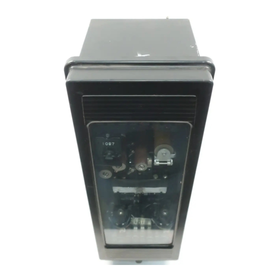
- Page 86 POLAR U N I T RM R EL A Y (AL) POLAR U N I T R E C E I V E R R E L AY CSG A UX I L IARY SWI TC H Fig. Type K A - 4 Relay Without Case. (Front Vi ew)
- Page 87 FRONT VIEW 629A4 7 6 629A389 Fig. 3 I n ternal Sch em atic of th e Type KA-4 R el a y for TC Fig. 2 I n ternal Schem atic of the Type KA-4 Relay for KR carrier set.
- Page 88 TY P E KA-4 CAR RI E R AU XI L I A RY R EL AY Squel c h U n i t TYPICAL TIME CURVE OF THE CARRIER-START OVERCURRENT UNIT OF THE TYPE KA- RELAY The function o f t h e squelch unit i s t o hold o ff carrier for a p eriod of 1 50 milliseconds after the Break er "a"...
- Page 90 TYP E KA-4 CAR RI E R AU X I L IARY R E LAY FO R R E L AYS TO B E U SE D WI TH A D J U S T M E N T S A N D M A l N T E N A NC E TC-TYP E CA R RI E R The p roper adj u stments to insure correct opera...
- Page 91 TY P E K A-4 CARRI E R AU X I L I ARY R EL AY termin al s . Increase the current until the contacts pl acing a screwdriver or similar tool into o n e of the pick up .
- Page 92 TY P E KA-4 CAR RI E R AU X I L I ARY R EL AY the indi c ator target when the current is between and CSP is located on the right hand pedestal of the 1 . 2 amperes d-e.
- Page 93 TY P E K A-4 CAR RI E R AU XI L I A RY R E LAY Al arm U n i t turns. Apply milliamp eres d . c . to the coil obs erv ing correct polarity, and then screw in the l eft hand C alibrate a s outlined above.
- Page 94 TY P E K A-4 CAR RI E R AUXI L I A RY R E LAY _, .,. ' "\ \ PAN EL CUTOUT & DRI LL I II G PAII E L LOCATI OII FOR S EM I FLUSH MTG. PROJECTIOII MTG.
- Page 96 WESTINGHOUSE ELECTRIC CORPORATION RELAY- INSTRUMENT D I V I S I ON NEWARK, N. J. Printed in U.S.A.
- Page 97 I N ST A L L A TI O N INST R UCT IONS TYPE KA-4 CARRIER AUXI LIARY R E LAY B efore putting relays into servi c e , remove The frame s erves as the mounting structure for...
- Page 99 TEINIMAl TEST SWITCH TERNIIIAL FRONT VIEW Fig. 3 I nternal S ch emati c of the Type KA-4 R elay for TC Fig. 2 I n ternal Schemati c of the Type KA-4 Relay for KR carrier set. carrier set.
- Page 100 TY P E K A-4 CA R RI E R AU XI L I ARY R EL AY Squel c h U n i t TYPICAL TIME CURVE OF THE CARRIER-START OVERCURRENT UNIT OF THE TYPE K A - RELAY The function of t h e squelch unit i s t o hold o ff 1 50 the carrier for a p eriod of...
- Page 102 TY P E KA-4 CAR RI E R AU X I L IARY R E LAY FO R R E L AYS TO B E U SE D WI TH A D J U S T M E N T S A N D M A l N T E N A NC E TC-TYP E CA R RI E R The proper adj u stments to in sure correct opera...
- Page 103 TYP E KA-4 CA R RI E R AUXI L I ARY R EL AY termin al s . Increase the current until the contacts placin g a screwdri ver or similar tool into o n e of the pick up.
- Page 104 TY P E KA-4 CAR RI E R AU X I L IARY R EL AY the indicator target when the current is between and CSP is located on the right hand pedest al of the 1. 2 amperes d-e.
- Page 105 TY P E K A-4 CAR RI E R AU XI L IA RY R E LAY Alarm U n i t turns. Apply milliamp eres d . c. to the coil observ ing correct pol arity, and then screw in the l eft hand Calibrate a s outlined abo v e .
- Page 108 WEST I NGHOUSE ELECTR I C CORPORAT I ON RELAY-INSTRUMENT DIVISION NEWARK, N. J. Printed in U.S.A.
- Page 109 M A I N TE N A N C E INSTR U CT IONS TYPE KA-4 CARRIER AUXI LIARY RELAY B efore putting relays into s ervi c e , remove T h e frame s erves a s the mounting structure for...
- Page 110 SQU E L C H U N I T P O L A R UNI T R E C E I V E R R E LAY CSG AUX I L I AR Y SWI TC H Fig. Type KA-4 Relay Without Case. (Front View)
- Page 111 TERNIMAL 62 9 A4 7 6 Fig. 3 I nternal Sch em a t i c of the Type KA-4 R elay for TC Fig. 2 I n ternal Schemati c o f the Type KA-4 Relay for K R carrier set.
- Page 112 TY P E KA-4 CAR RI E R AU XI L I A RY R EL AY Sque l c h U n i t TYPICAL TIME CURVE OF THE CARRIER-START OVERCURRENT UNIT OF THE TYPE KA- RELAY The function o f t h e s quelch unit i s t o hold o ff...
- Page 113 I . L . TY P E KA-4 CA RRI E R AU XI L I ARY R E LAY 4 1 -923.4C SHUN T ADD I T I ONAL FLUX PATti SALAHC�O A I K �A PS U M 8ALAMCED A I R �APS POLAR UN I T P E �AMEMT MAGN E T F LUX PATH S...
- Page 114 TY P E KA-4 CARRI E R AU XI L I ARY R E LAY FO R R E L AY S TO B E U S E D WI TH A D J U S T M E N T S A N D M A l N T E N A NC E TC-TYP E CAR RI E R The proper adj u stments to in sure correct op era...
- Page 115 TY P E K A-4 CARRI E R AU X I L I ARY R EL AY Increase the current until the contacts termin al s . placin g a screwdriver or similar tool into o n e of the pick up .
- Page 116 TY P E KA-4 CAR RI E R AU X I L IARY R EL AY the indicator target when the current is between 1 and and CSP is located on the right hand pedestal of the 1 . 2 amperes d-e.
- Page 117 TY P E K A-4 CARRI E R AUXH. I A RY R E LAY Al arm U n i t turns. Apply milliamp eres d . c . to the coil obs erv ing correct polarity, and then screw in the l eft hand Calibrate a s outlined abo ve.
- Page 118 Ot A. HOUS Olt CUT TEIMIJll AltO MOUNTING DElllLS CIROUT Pll � lOll MTG. 5 7- D-7903 F i g. O utline an d Drilling P l an fo r Type KA-4 R el ay in Type F T-42 C ase.
- Page 120 WESTINGHOUSE ELECTRIC CORPORATION RELAY-INSTRUMENT DIVISION NEWARK, N. J. Printed in U.S.A.
- Page 121 INSTRUCT IONS I N S T A L L A Tl O N TYPE KA-4 CARRIER AUXI LIARY RE LAY B efore putting relays into s ervi c e , remove The frame s erves as the mounting structure for...
- Page 123 TEST SWITCH TEitUUl TERNIMAL 629A4 7 6 Fig. 3 I n ternal Sch emati c of the Type KA-4 R elay for TC Fig. 2 I nternal Schem atic of the Type KA-4 Relay for KR carrier set. carrier set.
-
Page 124: Table Of Contents
TY P E KA-4 CAR RI E R AUXI L I ARY R EL AY ---- -- -- -- -- -- -- -- -- -- -- -- -- -- -- -- -- -- -- Sque l c h U n i t... - Page 125 TY P E KA-4 CA RRI E R AU X I L I ARY R E LAY SHUN T 6ALAN C tD A I � �APS U M BALAHCEO A I R �A P S POLAR UH I T P ERMANENT �AGH E T F LUX PATHS 183A062 Fig.
- Page 126 TY P E KA-4 CARRI E R AU XI L I ARY R E LAY FO R R E L AYS TO B E USED WI TH A D J U S T M E N T S A N D M A l N T E N A NC E TC-TYP E CA R RI E R The proper adju stm ents to in sure correct op era...
- Page 127 TYP E KA -4 CA R RI E R AU X I L I ARY R ELAY termin al s . Increase the current until the contacts placin g a screwdriver or similar tool into o n e of the pick up .
- Page 128 TY P E KA-4 CAR RI E R AU X I L IARY R EL AY the indicator target when the current is between 1 mid and CSP is located on the right hand pedest al of the 1 . 2 amperes d-e.
- Page 129 TY P E K A-4 CARRI E R AU XI L IA RY R E LAY Alarm U n i t turns. Apply milliamp eres d . c. to the coil obs erv ing correct polarity, and then screw in the l eft hand C alibrate a s outlined abov e .
- Page 132 W E STINGHOUS E E L E CTRIC CO R PO R ATION RELAY-INSTRUMENT DIVISION NEWARK, N. J. Printed in U.S.A.
- Page 133 In addition, there are two l ocating pins. The typ e KA-4 relay is an auxiliary relay u s ed The l o c ating pins are u s ed...
- Page 135 FRONT VIEW 629A4 7 6 Fig. 3 I n ternal Sch em atic of th e Type KA-4 R elay for TC Fig. 2 I nternal Schemati c a f th e Type KA-4 Relay fo r KR carrier set.
-
Page 136: 48V
TY P E K A-4 CA R RI E R AU XI L I ARY R EL AY Squel c h U n i t TYPICAL TIME CURVE OF THE CARRIER - START OVERCURRENT UNIT OF THE TYPE KA- RELAY The function o f t h e s quelch unit i s t o hold o ff the carrier for a p eriod of milliseconds after... -
Page 137: Csp Or Csg Coil
I . L . T Y P E KA-4 CA R RI E R AUXI L I A R Y R E LA Y 4 1 -92 3 . 4 8 SHUNT SALANC�D A I � �APS �MoALAM CEO A I R GAPS POLAR �M I T P E RMANENT MAGN E T F LUX PATHS... - Page 138 TY P E KA-4 CAR RI E R AU X I L I A RY R E LAY FO R R E L AYS TO B E U SE D WI TH A D J U S T M E N T S A N D M A l N T E N A NC E TC-TYP E CA R RI E R The proper adj u stments to insure correct opera...
- Page 139 TY P E K A-4 CA R RI E R AUXI L I ARY R EL AY termin al s. Increase the current until the contacts placing a screwdriver or similar tool into o n e of the notches located on the p eriphery o f th e spring adjust pick up .
- Page 140 TY P E KA-4 CAR RI E R AU X I L I ARY R EL AY the indicator target when the current is between 1 and and CSP is located on the right hand pedestal of the 1. 2 amperes d-e.
- Page 141 TY P E K A-4 CA R RI E R AU XI L I A RY R E LAY Al arm U n i t turns. Apply milliamp eres d . c . to the coil obs erv ing correct pol arity, and then screw in the l eft hand Calibrate a s outlined abo ve.
- Page 144 WEST I NGHOUSE E LECTR I C CORPORATION RELAY-INSTRUMENT DIVISION NEWARK, N. J. Printed in U.S.A.
Need help?
Do you have a question about the KA-4 and is the answer not in the manual?
Questions and answers