
Related Manuals for HP Z34c G3


Summary of Contents for HP Z34c G3
- Page 1 Maintenance and Service Guide Z34c G3 model SUMMARY This guide provides information about spare parts, removal and replacement of parts, diagnostic tests, problem troubleshooting, and more.
- Page 2 Devices, Inc. Bluetooth is a trademark sure to read “Important Safety Information”. owned by its proprietor and used by HP Inc. under license. NVIDIA is a trademark and/or registered trademark of NVIDIA Corporation in the U.S. and other countries.
-
Page 3: Table Of Contents
Table of Contents 1. Getting started ..................................2 Important safety information ............................. 2 Important service information and precautions ....................... 3 RoHS (2002/95/EC) requirements ........................... 3 General descriptions ................................4 Firmware updates ................................4 Before returning the repaired product to the customer ....................4 2. -
Page 4: Getting Started
1. Getting started Read this chapter to learn about safety information and where to find additional HP resources. Important safety information Carefully read the cautions and notes within this document to minimize the risk of personal injury to service personnel. The cautions and notes are not exhaustive. Proper service methods are important to the safe, reliable operation of equipment. -
Page 5: Important Service Information And Precautions
Important service information and precautions Repair must be performed by professional service technicians in a repair center. ● End users should not perform these procedures. Please note during servicing that the primary side is the high voltage area. ● This monitor meets ROHS requirements. Be sure to use lead-free solder wire ●... -
Page 6: General Descriptions
Level 2: Circuit board or standard parts replacement Firmware updates Firmware updates for the monitor are available at support.hp.com. If no firmware is posted, the monitor does not need a firmware update. Before returning the repaired product to the customer Perform an AC leakage current check on exposed metallic parts to be sure the product is safe to operate without the potential of electrical shock. -
Page 7: Monitor Features
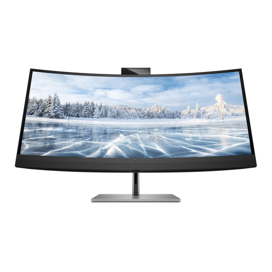
2. Monitor features This chapter provides an overview of the monitor’s features. Features Depending on the model, your monitor might include the following features: Display features 86.72 cm (34.14 in) diagonal viewable screen area with 3440 × 1440 resolution, ● plus full-screen support for lower resolutions;... - Page 8 Monitor stand Removable stand for flexible monitor head mounting solutions ● HP Quick Release 2 device to quickly attach the monitor head to the stand with a ● simple click, and then remove it with the convenient sliding tab release VESA®...
-
Page 9: Front Components
Front components To identify the power button on the front of the monitor, use this illustration. Table 1-1: Front components and their descriptions (1-2) Power button (with power light) USB port Battery charging 1.2 Microphones Camera light RGB lens IR lens IR lights... -
Page 10: Rear Components
Rear components To identify the components on the rear of the monitor, use this illustration and table. Table 1-2: Rear components and their descriptions Component Description OSD control Activates the OSD buttons so that the button labels appear on the right side of the screen. Security cable slot Connects an optional security cable. -
Page 11: Locating The Serial Number And Product Number
The SPEC label is located on the rear of the monitor. The serial number and product number are located on a SPEC label. You may need these numbers when contacting HP about the monitor model. For worldwide models (except India):... -
Page 12: Illustrated Parts Catalog
3. Illustrated parts catalog To identify the monitor major components, use this illustration and table. Table 2-1: Monitor major components and their descriptions Item Description DECO-CHIN Speaker PANEL ASSY RC MID FRAME SHD MAIN WEBCAM MODULE Main BD Power BD LED DRV BD HINGE CTRL BD... -
Page 13: How To Order Parts
You can purchase cables from the HP part store at https://partsurfer.hp.com/Search.aspx. NOTE: HP continually improves and changes product parts. For complete and current information about supported parts for your computer, go to http://partsurfer.com, select your country or region, and then follow the on-screen instructions. -
Page 14: Removal And Replacement Procedures
• Knife • Gloves • Cleaning cloth • ESD protection • Curve sponge Jig- CS.5J584.001 During assembly and disassembly, please place curve sponge jig to avoid damaging the panel. Item Qisda P/N Description Photo CS.4G584.001 SPONGE JIG Z34c G3 CURVE... -
Page 15: Rear Cover
Disassembly procedure Rear Cover 1) Disassemble RC from the monitor and pull out BTN BD wire from the Main BD. PICTURE 1 1) Unlock 6 screws and disassemble Hinge from the SHD as the picture 1. 2) Tear off the TOP Mylar, interface Mylar and Right Mylar from the SHD as the picture 1. - Page 16 PICTURE 2 PICTURE 3 1) Unlock 2 screws and disassemble USB BD from the MF as the picture 1. 2) Tear off the conduct sponge from the MF as the picture 2. 3) Tear off 4 acetate tapes from Panel as the picture 3. 4) Tear off the acetate tape from the camera wire as the picture 4.
- Page 17 PICTURE 3 PICTURE 4 1) Unlock 4 screws from the DECO as the picture 1. 1) Disassemble MF from the monitor as the picture 1. 2) Unlock 4 screws from the SPK as the picture 2. 3) Disassemble Power BD Mylar from the Power BD as the picture 3. PICTURE 1 PICTURE 2...
- Page 18 PICTURE 3 Main BD 1) Unlock 11 PCBA screws as the picture 1. 2) Disassemble Main BD from the SHD and pull out Power BD wire from the Main BD. 3) Disassemble Power BD from the SHD and pull out power cord from the Power BD. PICTURE 1 Main BD Power BD...
-
Page 19: Power Board
Power BD PN Power Board IMPORTANT: • Repairing must operate by professional repairers in HP repair center, not applicable for end user • The primary side is the high voltage area, please take care when repair (Front and Back view) -
Page 20: Power Board- Capacitor Repair
Power board- Capacitor repair Repair Condition: Capacitor repair is only for the monitor that has been out of warranty period. IMPORTANT: • Repairing must operate by professional repairers (Note) in repair center, not applicable for end user • The primary side is the high voltage area, please take care when repair (Front and Back view) •... - Page 21 Repair Process: When EL capacitors damage or explode, it may lose function and cause product no work. The locations are identified below: Power Board C711; C712; C713; C714 C706; C707 1) You must disconnect the power cord from the power source before opening the monitor to prevent component damage.
- Page 22 3) Lift capacitors from the PCB. Power Board 4) Place new component on the location, and must check polarity match PCB print. 5) After repaired, please double check whether polarity match PCB print, solder empty and unnecessary solder after soldering must remove.
-
Page 23: Connector Repair
Connector repair Repair Condition: Connector repair is only for the monitor that has been out of warranty period. • The repair procedure is for HDMI, RJ45 and USB Type B connectors. • The connectors are on the main board (Main board part number 5E.58401.001). •... - Page 24 IMPORTANT: • Repair Condition: Connector repair is only for out of warranty. • Repairing must operate by professional repairers (Note) in repair center, not applicable for end user. • Electrostatic protection is required when component replacement is required. • The monitor meets ROHS, please use Lead-free solder wire for soldering. •...
-
Page 25: Hdmi Connector Repair- J401
HDMI Connector repair- J401 1) Use a soldering iron and a de-soldering pump to remove as much solder as possible from one of the pin. 2) Use a hot air gun to melt the solder on the pins 3) Lift connector from the PCB 4) Place new component on the location, and must check it can match PCB footprint 5) Soldering the new component by solder iron... -
Page 26: Rj45 Connector Repair- Jf1
RJ45 Connector repair- JF1 1) Use a hot air gun to melt the solder on the pins Pin solder with soldering iron and absorber. 2) You can gently push down with the soldering iron once everything is molten to move the connector out of the through holes 3) Lift connector from the PCB 4) Place new component on the location, and must check it can match PCB footprint... -
Page 27: Usb Type B Connector Repair- Ja1
USB Type B Connector repair- JA1 1) Use a hot air gun to melt the solder on the pins Pin solder with soldering iron and absorber. 2) You can gently push down with the soldering iron once everything is molten to move the connector out of the through holes 3) Lift connector from the PCB 4) Place new component on the location, and must check it can match PCB footprint... -
Page 28: Function Test
Function Test: After repair, be sure to confirm that all functions are working. Table 4-1: Function test Test item Operating description Tool used HDMI test Confirm whether image displays and sound Computer or DVD player plays correctly on the monitor. Network test Plug in network wire and RJ45 green light on. -
Page 29: Support And Troubleshooting
Support and Troubleshooting The following table lists possible problems, the possible cause or each problem, and the recommended solutions. Table 4-2: Solving common problems Problem Possible cause Solution Screen is blank Power cord is disconnected. Connect the power cord. or video is flashing. -
Page 30: Index
Index button ............... 7, 8, 27 parts ..................10 Power board ............11, 17, 18 Power connector ............... 8 Camera light ..............7 precautions ................ 3 Connector repair............21, 22 preparation for disassembly ..........12 DisplayPort connector ............. 8 RC removal ..............13 Rear components .............
Need help?
Do you have a question about the Z34c G3 and is the answer not in the manual?
Questions and answers