
Related Manuals for Samsung AC BN DCH Series


Summary of Contents for Samsung AC BN DCH Series
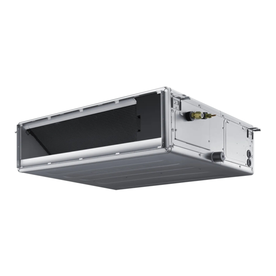
- Page 1 Air conditioner Installation manual AC***BN*DCH • Thank you for purchasing this Samsung air conditioner. • Before operating this unit, please read this manual carefully and retain it for future reference.
-
Page 2: Table Of Contents
Contents Safety Information Installation Procedure Step 1 Checking and preparing accessories Step 2 Choosing the installation location Step 3 Optional: Insulating the body of the indoor unit Step 4 Installing the indoor unit Step 5 Purging inert gas from the indoor unit Step 6 Cutting and flaring the pipes Step 7 Connecting the assembly pipes to the refrigerant pipes Step 8 Performing the gas leak test... -
Page 3: Safety Information
• This manual explains how to install an indoor unit with a split • Always disassemble the electric lines before the system with two SAMSUNG units. The use of other types refrigerant tubes. of units with different control systems may damage the •... - Page 4 Safety Information • After completing the installation, always carry out a • functional test and provide the instructions on how to supply comply with the specifications and that the operate the air conditioner to the user. installed power is sufficient to ensure the operation of any other domestic appliance connected to the same •...
-
Page 5: Installation Procedure
Installation Procedure Step 1 Checking and preparing Step 2 Choosing the installation location accessories Installation location requirements The following accessories are supplied with the indoor unit. The • There must be no obstacles near the air inlet and outlet. • Install the indoor unit on a ceiling that can support its weight. User manual (1) Installation manual (1) •... - Page 6 Installation Procedure Spacing requirements Construction Standard for Inspection opening ceiling. a. Height is more than 1.64ft (0.5m): Only “B” [Inspection for PBA] is applied. Unit Width(W) "A"=W+3.94 inch (100 mm) "B"=19.69 inch (500 mm) 0.79 inch (20 mm) or more 0.79 inch (20 mm) or more •...
- Page 7 Unit : inch(mm) AC009BNLDCH/AC012BNLDCH 30. 1 6(766) 0.79(20) 4. 9 6(126) 1.38(35) 5.75(146) 6. 1 0(155) 5 . 1 2(130) 1.38(35) 5.47(139) 0.51(13) 1.30(33) 6. 9 3(176) 10.83(275) 10.83(275) 30.63(778) 31.73(806) 37.21(945) (Suspension position) 7X3. 9 4=27.56 (7X100=700) 29.32(742) (Air outlet duct flange) (Air around) 35.43(900) Inspection hole...
- Page 8 Installation Procedure AC018BNLDCH Unit : inch(mm) 0.79(20) 38.03(966) 0.51(13) 1.38(35) 2.76(70) 8.58(218) 2.83(72)1.38(35) 8.39(213) 12.72(323) 0.33(8.3) 5. 1 2(130) 10.83(275) 10.83(275) 10.83(275) 38.50(978) 39.61(1006) (Suspension position) 45.08(1145) 9x3. 9 4=35.43(9x100=900) 24-Ø0.14(3.5) 37 .09(942) (Air outlet duct flange) (Air around) inspection hole 43.31(1100) 43.31(1100) 19.69(500)
- Page 9 AC009BNHDCH/AC012BNHDCH Unit : inch(mm) hole 7x3.94=27.56(7x100=700) Ø 0.13(3.2) (Air around) (Air outlet duct flange) 32.17(817) 33.46(850) Inspection hole (Suspension position) 35.43(900) 33.46(850) 37.40(950) 19.69(500) 8.39(213) 4.92(125) Suction side 13.39(340) Discharge side Name Description Ø1/4 inch (6.35 mm) Gas pipe connection Ø3/8 inch (9.52 mm) Drain pipe connection 3/4 inch (OD 1.05 inch (26.67 mm ))
- Page 10 Installation Procedure AC018BNHDCH/ AC024BNHDCH/ AC030BNHDCH Unit : inch(mm) 11x3.94=43.31(11x100=1100) hole Ø 0.13(3.2) (Air outlet duct flange) 45.94(1167) (Air around) 47.24(1200) (Suspension position) 49.21(1250) Inspection hole 47.24(1200) 51.18(1300) 19.69(500) 8.39(213) 4.92(125) 13.39(340) Suction side Discharge side Description Name AC018BNHDCH AC024BNHDCH AC030BNHDCH Ø1/4 inch (6.35 mm) Ø3/8 inch (9.52 mm) Gas pipe connection...
- Page 11 AC036BNHDCH/AC042BNHDCH/AC048BNHDCH Unit : inch(mm) 11x3.94=43.31(11x100=1100) hole Ø 0.13(3.2) (Air outlet duct flange) 49.92(1268) (Air around) 51.18(1300) 53.15(1350) (Suspension position) Inspection hole 51.18(1300) 55.12(1400) 19.69(500) 8.39(213) 4.92(125) 13.39(340) Discharge side Suction side Name Description Ø3/8 inch (9.52 mm) Gas pipe connection Ø5/8 inch (15.88 mm) Drain pipe connection 3/4 inch (OD 1.05 inch (26.67 mm ))
-
Page 12: Step 3 Optional: Insulating The Body Of The Indoor Unit
Installation Procedure Step 3 Optional: Insulating the body of NOTE the indoor unit • Insulate the end of the pipe and some curved area by using separate insulator. • Insulate the discharge and suction part at the same time when you insulate connection duct. Back Step 4 Installing the indoor unit When deciding on the location of the air conditioner with the... - Page 13 3 Install the suspension bolts depending on the ceiling type. CAUTION ( 3mm ) • Ceiling support slant to the left or right side of the unit which will be connected with the drain hose, as shown in the figure. Make a tilt when you wish to install the drain pump, too.
-
Page 14: Step 5 Purging Inert Gas From The Indoor Unit
Installation Procedure Step 5 Purging inert gas from the indoor CAUTION unit • Connect the indoor and outdoor units using pipes with flared degreased and deoxidized copper pipe (Cu DHP type to ISO 1337 nitrogen gas. (inert gas) Therefore, all inert gas must be purged or UNI EN 12735-1), suitable for operating pressures of at least before connecting the assembly piping. -
Page 15: Step 7 Connecting The Assembly Pipes To The Refrigerant Pipes
Step 7 Connecting the assembly pipes to Outer Diameter (D) Depth (A) Flare dimension (L) the refrigerant pipes Ø1/4 (6.35) 0.051 (1.3) 0.34~0.36 (8.7~9.1) There are two refrigerant pipes of different diameters : Ø3/8 (9.52) 0.071 (1.8) 0.50~0.52 (12.8~13.2) • Ø1/2 (12.70) 0.079 (2.0) 0.64~0.65 (16.2~16.6) -
Page 16: Step 8 Performing The Gas Leak Test
Installation Procedure 2 Be sure to use insulator which is thick enough to cover the Step 8 Performing the gas leak test refrigerant tube to protect the condensate water on the outside of pipe falling onto the floor and the efficiency of the unit will be Pressure check the refrigerant system using high pressure better. -
Page 17: Step 9 Insulating The Refrigerant Pipes
Step 9 Insulating the refrigerant pipes CAUTION Once you have checked that there are no leaks in the system, you • Make sure that all refrigerant connection must be accessible can insulate the piping and hose. for easy maintenance and detachment. To avoid condensation problems, place Acrylonitrile Butadien •... - Page 18 Installation Procedure Insulation Type (Cooling, Heating) General High humidity Outer diameter [86°F(30°C), 85%] [86°F(30°C), over 85%] Pipe Remarks EPDM, NBR inch inch inch 6.35~9.52 1/4~3/8 12.7~50.80 1/2~2 6.35 The internal temperature is 9.52~25.4 3/8~1 Gas pipe 1 1/4 28.58~44.45 1 1/8~1 3/4 1 1/2 50.8 •...
-
Page 19: Step 10 Installing The Drain Hose And Drain Pipe
Step 10 Installing the drain hose and drain Without the drain pump pipe Install horizontal drainpipe with a slope of 1/100 or more and fix Push the supplied drain hose as far as possible over the drain it by hanger space of 3.28~4.92ft(1~1.5m). socket. -
Page 20: Step 11 Performing The Drainage Test
Installation Procedure Centralized drainage without the drain pump Step 11 Performing the drainage test Prepare a little water about 0.53 gallons(2 liters). Install horizontal drainpipe with a slope of 1/100 or more and fix 1 Loosen screws and take out the side cover plate. it by hanger space of 3.28~4.92ft(1~1.5m). -
Page 21: Step 12 Optional: Installing External Controller
Step 12 Optional: Installing external Step 13 Connecting the power and controller communication cables CAUTION Accessories (External controller : MIM-B14) • Always remember to connect the refrigerant pipes before performing the electric connections. When disconnecting External Controller PCB Case the system, always disconnect the electric cables before disconnecting the refrigerant pipes. - Page 22 Installation Procedure AC***BNHDCH AC***BNHDCH Communication: M3.5 screw AC power: M4 screw Indoor Unit 0.35(9) 0.50(12.6) F1 F2 0.30(7.5) 0.39(9.8) Unit : inch(mm) Cable clamp Tightening torque lbf·ft (kgf • cm) M3.5 0.58 to 0.87 (8.0 to 12.0) Outdoor Unit 0.87 to 1.30 (12.0 to 18.0) 1(L) 2(N) L •...
-
Page 23: Step 14 Optional: Extending The Power Cable
Step 14 Optional: Extending the power 3 Insert both sides of core wire of the power cable into the connection sleeve. cable • Method 1: Push the core wire into the sleeve from both sides. Prepare the following tools. • Method 2: Twist the wire cores together and push it into the sleeve. -
Page 24: Step 15 Setting Additional Functions Of Wired Remote Control
Installation Procedure 6 Wrap it with the insulation tape twice or more and position your Step 15 Setting additional functions of contraction tube in the middle of the insulation tape. wired remote control Automatic Air-Volume (This function can't be used at Method 2 Method 1 AC***BNLDCH model) - Page 25 External Static Pressure (ESP) setting for phase 4 Press the button to select 1 to enable automatic air- volume operation. control motor 5 Select mode No. 8.2 , and set to “1”. With its phase control motor, you can adjust the indoor unit fan 6 Press the button, then the air conditioning unit will start the speed depending on the installation condition.
- Page 26 Installation Procedure Model AC018BNHDCH AC024BNHDCH Model AC042BNHDCH AC048BNHDCH Static Pressure Option Code for Indoor Unit Static Pressure Option Code for Indoor Unit 277D8A-370045 278C9B-370045 277D8A-370045 278C9B-370045 277D8A-370045 278C9B-370045 277D8A-370045 278C9B-370045 12.5< 277D8A-370045 278C9B-370045 15< 277D8A-370045 278C9B-370045 17.5< 277D8A-370045 278C9B-370045 Model AC030BNHDCH AC036BNHDCH NOTE...
- Page 27 EASY Tuning If the more cooling and heating airflow rate which set up when installing is wanted, or if the more Silent operation which sets up when installing is wanted, air conditioner is tuned for comfort. Indoor unit airflow rate for high, mid, low mode increases or decreases for +2 ~ -2 Steps with wired remotecontrol.
-
Page 28: Step 16 Optional : Setting The Emergency Temperature Output (Eto) Function
Installation Procedure Step 16 Optional : Setting the Emergency Temperature Output (ETO) function Emergency Temperature Output (ETO) function (for the multi system, this function is not supported.) CAUTION • In order to deploy the ETO function, the MIM-B14, an external contact interface module, must be installed in each indoor unit. –... - Page 29 [Main] [Sub] ETO operation specifications Main indoor unit – Based on the external contact control settings, the main indoor unit decides whether to generate output when an error (indoor unit stop) occurs. – Based on the ETO settings, the main indoor unit decides whether to generate output according to the temperature and time conditions. 2 Sub indoor unit –...
-
Page 30: Step 17 Setting The Indoor Unit Option Code With Wired Remote Controller
Installation Procedure Step 17 Setting the indoor unit option code with Press the buttons at the same time for more than 3 seconds and then a Main menu will be displayed. wired remote controller In order to set the indoor unit option code use the wired remote controller 2 Press the button to select and then press... - Page 31 seconds and then a Main menu will be displayed. 3 seconds and then a Main menu will be displayed. 2 Press the button to select and then press Press the button to select and then press button to enter a Sub-menu setting screen. button to enter a Sub-menu setting screen.
-
Page 32: Step 19 Optional :Setting The Indoor Unit Addresses And The Installation Options With Wireless Remote Controller
Installation Procedure Step 19 Optional : Setting the indoor unit 2 Set the option values. addresses and the installation options with CAUTION wireless remote controller • The total number of available options are 24: SEG1 to SEG24. You cannot set both the indoor unit addresses and the •... - Page 33 Take the steps presented in the following table: Steps Remote control display 1 Set the SEG2 and SEG3 values: a Set the SEG2 value by pressing the value you want to set appears on the remote control display. SEG2 b Set the SEG3 value by pressing the value you want to set appears on the remote control display.
- Page 34 Installation Procedure Steps Remote control display (Mode) button. Fan and On appear on the remote control display. 6 Press the 7 Set the SEG9 and SEG10 values: a Set the SEG9 value by pressing the value you want to set appears on the remote control display. SEG9 b Set the SEG10 value by pressing the value you want to set appears on the remote control display.
- Page 35 Steps Remote control display 11 Set the SEG14 and SEG15 values: a Set the SEG14 value by pressing the value you want to set appears on the remote control display. SEG14 b Set the SEG15 value by pressing the value you want to set appears on the remote control display. When you press the SEG15 following order:...
- Page 36 Installation Procedure Steps Remote control display (Mode) button. Fan and Off appear on the remote control display. 16 Press the 17 Set the SEG21 and SEG22 values: a Set the SEG21 value by pressing the value you want to set appears on the remote control display. SEG21 b Set the SEG22 value by pressing the value you want to set appears on the remote control display.
- Page 37 3 Check whether the option values that you have set are correct by pressing the (Mode) button repeatedly [SEG2, SEG3] [SEG4, SEG5] [SEG6, SEG8] [SEG9, SEG10] [SEG14 , SEG15] [SEG16 , SEG17] [SEG18 , SEG20] [SEG11 , SEG12] [SEG21 , SEG22] [SEG23, SEG24] 4 Save the option values into the indoor unit: Point the remote control to the remote control sensor on the indoor unit and then press the...
- Page 38 Installation Procedure Setting the indoor unit address and installation option 1 Make sure that the power is supplied to the indoor unit. • If the indoor unit is not plugged in, it must include a power supply. 2 Set an address and installation option for each indoor unit using the remote control, according to your air conditioning system plan. Setting an indoor unit address (MAIN/RMC) •...
- Page 39 Setting the installation options • The installation options of indoor units are set to 020010-120000-200000-300000 by default. Option No. : 02XXXX-1XXXXX-2XXXXX-3XXXXX Option SEG1 SEG2 SEG3 SEG4 Use of external room temperature sensor / Explanation PAGE MODE Minimizing fan operation when thermostat is off Indication Details Indication...
- Page 40 Installation Procedure Installation Procedure Option SEG9 SEG10 SEG11 SEG12 Explanation Use of Hot Coil Use of auxiliary heater Controller variables for auxiliary heater Indication Details Indication Details Details Time Indication temperature delay for for auxiliary auxiliary heat on heat on temperature No delay offset...
- Page 41 Option SEG13 SEG14 SEG15 SEG16 Setting the output of external Explanation PAGE Use of external control control Indication Details Indication Details Indication Details Disuse Sub, On/Off Existing Control Window Thermo Disuse Main, On/Off Existing Control RESERVED Indication Window and Details Disuse Sub, On/Off...
-
Page 42: Appendix
Troubleshooting • If an error occurs during the operation, one or more LED flickers and the operation is stopped except the LED. • If you re-operate the air conditioner, it operates normally at first, then detect an error again. Indicators Concealed Type Abnormal conditions Remarks... - Page 43 • If an error occurs, is displayed on the wired remote controller. If you would like to see an error code, press the Test button. Display Explanation Remark Communication Error between indoor and outdoor unit Error of Room sensor in the indoor unit(Open/Short) Error of Eva In sensor in the indoor unit(Open/Short) Error of Eva Out sensor in the indoor init(Open/Short) 2nd Detection of the float switch...
Need help?
Do you have a question about the AC BN DCH Series and is the answer not in the manual?
Questions and answers