Table of Contents
Advertisement
Quick Links
Advertisement
Table of Contents

Related Manuals for Asus Q470EI-IM-A


Summary of Contents for Asus Q470EI-IM-A
- Page 1 Q470EI-IM-A...
- Page 2 Product warranty or service will not be extended if: (1) the product is repaired, modified or altered, unless such repair, modification of alteration is authorized in writing by ASUS; or (2) the serial number of the product is defaced or missing.
-
Page 3: Table Of Contents
Contents Chapter 1 Product overview Package contents................. 1-1 Features ..................1-1 Specifications ................1-2 Chapter 2 Motherboard information Before you proceed ..............2-1 Motherboard layout ..............2-2 Central Processing Unit (CPU) ........... 2-4 2.3.1 CPU installation .............. 2-5 2.3.2 CPU heatsink and fan assembly installation ....2-7 System memory ................ - Page 4 3.3.14 NVMe Configuration ............3-14 3.3.15 Onboard Devices Configuration ........3-14 3.3.16 EZ-Flash ............... 3-15 3.3.17 APM Configuration ............3-15 3.3.18 Watchdog Timer ............3-16 3.3.19 Miscellaneous ............... 3-16 Hardware Monitor menu ............3-17 3.4.1 Smart Fan Mode ............3-17 3.4.2 Smart Fan Function ............
-
Page 5: Chapter 1 Product Overview
Chapter 1 Product overview Package contents Check your industrial motherboard package for the following items. 1 x ASUS Q470EI-IM-A Motherboard 2 x Serial ATA 6.0 Gb/s cables 2 x M.2 screw packages 1 x ASUS I/O Shield NOTE: If any of the above items is damaged or missing, contact your distributor or sales representative immediately. -
Page 6: Specifications
1 x USB 3.2 Gen 1 port 4 x USB 2.0 ports Rear panel I/O ports 2 x LAN (RJ45) ports 1 x P/S2 keyboard port 1 x P/S2 mouse port 1 x COM port (RS232/422/485) 2 x Audio jacks (continued on the next page) Q470EI-IM-A... - Page 7 4 x COM Port headers (1 x RS232/422/485, 3 x RS232) 1 x USB 3.2 Gen 1 connector supports additional 2 USB 3.2 Gen 1 ports 1 x USB 3.2 Gen 1 stick socket 1 x USB 2.0 connector supports additional 2 USB 2.0 ports 1 x CPU Fan connector with PWM mode 1 x Chassis Fan connector with PWM mode 1 x Disable ME connector...
- Page 8 OS support RedHat Enterprise Fedora Workstation OpenSUSE Certification CE, FCC, UL Mini-ITX Form Factor, 6.7”x 6.7” (17.0cm x 17.0cm) Form Factor NOTE: Specifications are subject to change without notice. Please refer to the ASUS website for the latest specifications. Q470EI-IM-A...
-
Page 9: Chapter 2 Motherboard Information
Chapter 2 Motherboard information Before you proceed Take note of the following precautions before you install motherboard components or change any motherboard settings. CAUTION! • Unplug the power cord from the wall socket before touching any component. • Before handling components, use a grounded wrist strap or touch a safely grounded object or a metal object, such as the power supply case, to avoid damaging them due to static electricity. -
Page 10: Motherboard Layout
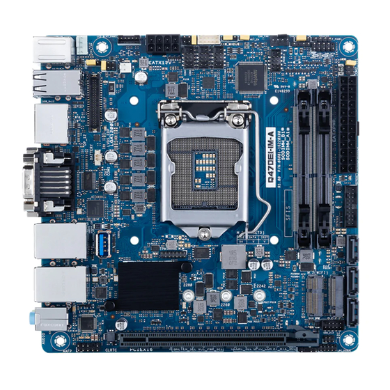
Super PANEL_SW USB_9~12 DP_12 LGA1200 Place this side towards the rear of the chassis 210AT LAN2_U32G1_3 PCIE SATA IRST U32G2_C1 M.2(SOCKET3) 128Mb BIOS Intel ® LAN1_U32G2_45 Q470E 2280 2260 2242 219LM AUDIO USB_213 ALC887 ALC897 PCIEX16 CLRTC SPDIF_OUT LPC_DEBUG Q470EI-IM-A... - Page 11 Page Connectors/Jumpers/Slots CPU and chassis fan connectors (4-pin CPU_FAN, 4-pin CHA_FAN) 2-18 Display panel VCC power selection (6-pin VCC_PWR_SEL) 2-10 LVDS/eDP Backlight panel connector (5-pin LCD_BLKT_PANEL) 2-23 Intel LGA1200 CPU socket ® ATX power connectors (24-pin EATXPWR, 8-pin EATX12V) 2-25 COM1/2 Ring/+5V/+12V selection jumpers (6-pin COM1_SEL, COM2_SEL) 2-10 General purpose input/output connector (10-pin GPIO_CON)
-
Page 12: Central Processing Unit (Cpu)
Return Merchandise Authorization (RMA) requests only if the motherboard comes with the cap on the LGA1200 socket. • The product warranty does not cover damage to the socket contacts resulting from incorrect CPU installation/removal, or misplacement/loss/ incorrect removal of the PnP cap. Q470EI-IM-A... -
Page 13: Cpu Installation
2.3.1 CPU installation Chapter 2: Motherboard information... - Page 14 Q470EI-IM-A...
-
Page 15: Cpu Heatsink And Fan Assembly Installation
2.3.2 CPU heatsink and fan assembly installation CAUTION! Apply the Thermal Interface Material to the CPU heatsink and CPU before you install the heatsink and fan if necessary. To install the CPU heatsink and fan assembly Chapter 2: Motherboard information... - Page 16 To uninstall the CPU heatsink and fan assembly Q470EI-IM-A...
-
Page 17: System Memory
System memory This motherboard comes with two Double Data Rate 4 (DDR4) Small Outline Dual Inline Memory Module (SO-DIMM) sockets. The figure below illustrates the location of the DDR4 SO-DIMM sockets: Channel Sockets Channel A SO-DIMM_B1* Channel B SO-DIMM_A1* Recommended memory configuration DIMM_A1* DIMM_B1* DIMM_A1*... -
Page 18: Jumpers
(Default) Setting Pins 3V (Default) Connector type HEADER 2 x 3p, 2.54mm pitch, S/T COM1/2 Ring/+5V/+12V selection (6-pin COM1_SEL, COM2_SEL) COM1_SEL +12V (Default) COM2_SEL +12V (Default) Setting Pins +12V Ring (Default) Connector type HEADER 2x3p, 2.54mm pitch, S/T Q470EI-IM-A 2-10... - Page 19 AT/ATX mode selection (3-pin AT_ATX_SEL) AT_ATX_SEL ATX mode AT mode (Default) Pins 1-2 (Default) ATX mode AT mode Connector type HEADER 1x3p, 2.54mm pitch, S/T WDT Enable jumper (2-pin WDT_EN) A watchdog timer is an electronic timer that is used to detect and recover from computer malfunctions.
- Page 20 By default, the pin labeled “Chassis Signal” and “Ground” are shorted with jumper caps. Remove the jumper caps only when you intend to use the chassis intrusion detection feature. CHASSIS PIN 1 Connector type HEADER 4p, K2, 2.54mm pitch Q470EI-IM-A 2-12...
- Page 21 Clear CMOS header (2-pin CLRTC) This header allows you to clear the CMOS RTC RAM data of the system setup information such as date, time, and system passwords. CLRTC Connector type HEADER 1x2p, 1.25mm pitch, S/T To erase the RTC RAM: Turn OFF the computer and unplug the power cord.
-
Page 22: Connectors
DVI-D can not be converted to output from RGB Signal to CRT and is not compatible with DVI-I. ). This Universal Serial USB 3.2 Gen 2 (up to 10Gbps) port (USB Type-C ® Bus (USB) port is for a USB 3.2 Gen 2 Type-C device. ® Q470EI-IM-A 2-14... - Page 23 10. USB 3.2 Gen 1 (up to 5Gbps) port. This 9-pin Universal Serial Bus (USB) port is for a USB 3.2 Gen 1 device. • USB 3.2 Gen 1 devices can only be used for data storage. • We strongly recommend that you connect USB 3.2 Gen 1 devices to USB 3.2 Gen 1 ports for faster and better performance from your USB 3.2 Gen 1 devices.
-
Page 24: Internal Connectors
IntA_P1_SSRX+ IntA_P2_SSRX- IntA_P2_SSRX+ IntA_P1_SSTX- IntA_P2_SSTX- IntA_P1_SSTX+ IntA_P2_SSTX+ IntA_P1_D- IntA_P2_D- IntA_P1_D+ IntA_P2_D+ Connector type BOX HD 2x10p, K20, 2.0mm pitch USB3.2 Gen 1 port (U32G1_6) This Universal Serial Bus (USB) port is for USB 3.2 Gen 1 devices. U32G1_6 Q470EI-IM-A 2-16... - Page 25 USB 2.0 connector (10-1 pin USB213) This connector is for an USB 2.0 port. Connect the USB cable to this connector. This USB connector complies with USB 2.0 specification that supports up to 480 Mbps connection speed. USB_213 PIN 1 Connector type Header 2x5p, K9, 2.0mm pitch CAUTION! Never connect a 1394 cable to the USB connector.
- Page 26 Serial Peripheral Interface (SPI), allowing you to securely store keys, digital certificates, passwords and data. A TPM system also enhances network security, protects digital identities, and ensures platform integrity. PIN 1 Connector type Header 2x7p, K14, 2.0mm pitch Q470EI-IM-A 2-18...
- Page 27 Front panel system panel connector (10-1 pin F_PANEL) This connector supports several chassis-mounted functions. +PWR_LED PWR_BTN F_PANEL PIN 1 +HDD_LED RESET Connector type Header 2x5p, K10, 2.54mm pitch • System power LED (2-pin +PWR_LED) This 2-pin connector is for the system power LED. Connect the chassis power LED cable to this connector.
- Page 28 WAFER HD 2x20p, 1.25mm pitch 11. Speaker connector (4-pin SPEAKER) The 4-pin connector is for the chassis-mounted system warning speaker. The speaker allows you to hear system beeps and warnings. SPEAKER PIN 1 Connector type HEADER 1x4p, 2.54mm pitch, S/T Q470EI-IM-A 2-20...
- Page 29 12. RTC Battery connector (2-pin BATTERY) This connector is for the lithium CMOS battery. BATTERY +BAT PIN 1 13. M.2 socket 3 This socket allows you to install an M.2 SSD module. M.2(SOCKET3) NOTES: • The M.2 SSD module is purchased separately. •...
- Page 30 IMPORTANT! • Scan the QR code to view the meaning of each debug code. • Debug codes are only available for ASUS LPC debug card. • Contact your region sales representative for LPC debug header ordering. C connector (6-pin I2C)
- Page 31 17. Serial port connectors (10-1 pin COM2, COM3, COM4, COM5) These connectors are for serial (COM) ports. Connect the serial port cables to these connectors, then install the module to a slot opening at the back of the system chassis. COM3 COM4 COM5...
- Page 32 • If you want to connect a high-definition front panel audio module to this connector, set the HD Audio Controller item in the BIOS Setup to [Enabled]. Q470EI-IM-A 2-24...
- Page 33 21. ATX power connectors (24-pin EATXPWR, 8-pin EATX12V) Correctly orient the ATX power supply plugs into these connectors and push down firmly until the connectors completely fit. EATX12V EATXPWR +3 Volts +12 Volts +5 Volts PIN 1 +12 Volts +5 Volts +5V Standby +5 Volts Power OK...
- Page 34 Q470EI-IM-A 2-26...
-
Page 35: Chapter 3 Bios Setup
Always shut down the system properly from the operating system. IMPORTANT! • Visit the ASUS website at www.asus.com to download the latest BIOS file for this motherboard. • The default BIOS settings for this motherboard apply to most working conditions and ensures optimal performance. -
Page 36: Main Menu
3.3.1 LVDS Configuration Switch to LVDS Configuration options: [Disable] [Enable] All-in-One Chassis Allows you to select All-in-One (AiO) Chassis (if applicable) for simplified AiO configuration. Configuration options: [None] [1920*1080 LVDS1] [1920*1080 LVDS2] [1920*1080 LVDS3] [1600*900 LVDS4] Q470EI-IM-A... - Page 37 • Be cautious when selecting AiO chassis. Incorrect selection of AiO chassis can cause incorrect operation or potential damage to AiO chassis hardware. • The following items appear only when you set All-in-One Chassis to [None]. EDID Data Source Configuration options: [Pre-Defined] [Flat Panel Display] The following item appears when you set EDID Data Source to [Pre-Defined].
-
Page 38: Pch-Fw Configuration
Allows you to schedule an operation for security device. Configuration options: [None] [TPM Clear] Your computer will reboot during restart in order to change the state of security device. Platform Hierarchy Configuration options: [Disabled] [Enabled] Storage Hierarchy Configuration options: [Disabled] [Enabled] Endorsement Hierarchy Configuration options: [Disabled] [Enabled] Q470EI-IM-A... -
Page 39: Cpu Configuration
TPM 2.0 UEFI Spec Version Allows you to select the TCG2 Spec Version support. Configuration options: [TCG_1_2] [TCG_2] [TCG_1_2] Support the compatible mode for Win8/Win10. [TCG_2] Support new TCG2 protocol and event format for Win10 or later. Physical Presence Spec Version Allows you to select to tell O.S. -
Page 40: Graphics Configuration
Keeps IGFX enabled base on the setup options. [Disabled] Disables internal graphics. [Enabled] Enables internal graphics. 3.3.6 PCI Express Configuration This item allows you to configure PCI Express settings. HYPER_PCIeX16 Configuration options: [PCIe x16 mode] [PCIe x8/x8 mode] [PCIe x8/x4/x4 mode] Q470EI-IM-A... - Page 41 PCIe x16/x8 Slot Allows you to configure the PEG Port settings. PEG 0:1:0 Enable Root Port Allows you to enable or disable the Root Port. Configuration options: [Disabled] [Enabled] [Auto] Max Link Speed Allows you to configure PEG 0:1:0 Max Speed. Configuration options: [Auto] [Gen1] [Gen2] [Gen3] Max Link Width Allows you to force PEG link to restrain to X1/2/4/8.
-
Page 42: Amt Configuration
Unconfigure ME Allows you to unconfigure ME by resetting the MEBx password to default. Configuration options: [Disabled] [Enabled] 3.3.8 CSM Configuration CSM Support Allows you to enable or disable CSM (Compatibility Support Module) Support. Configuration options: [Disabled] [Enabled] Q470EI-IM-A... -
Page 43: Super Io Configuration
The following items appear only when you set CSM Support to [Enabled]. GateA20 Active Configuration options: [Upon Request] [Always] [Upon Request] GA20 can be disabled using BIOS services. [Always] Do not allow disabling GA20, which functions when any RT code is executed above 1MB. Network Allows you to control the execution of UEFI and Legacy Network OpROM. -
Page 44: Serial Console Redirection
Allows you to select serial port transmission speed. The speed must be matched on the other side. Long or noisy lines may require lower speeds. Configuration options: [9600] [19200] [38400] [57600] [115200] Data Bits Configuration options: [7] [8] Q470EI-IM-A 3-10... - Page 45 Parity A parity bit can be sent with the data bits to detect some transmission errors. Configuration options: [None] [Even] [Odd] [Mark] [Space] [None] Disables parity check. [Even] Parity bit is 0 if the num of 1’s in the data bits is even. [Odd] Parity bit is 0 if the num of 1’s in the data bits is odd.
-
Page 46: Sata And Rst Configuration
This option only takes effect if SATA controller is in RAID mode. Configuration options: [Msix] [Msi] [Legacy] RAID Device ID Allows you to choose RAID device ID. Configuration options: [Client] [Alternate] Aggressive LPM Support Allows you to enable PCH to aggressively enter link power state. Configuration options: [Disabled] [Enabled] Q470EI-IM-A 3-12... -
Page 47: Network Stack Configuration
Serial ATA Port 1(~3) Port 1(~3) Allows you to enable or disable SATA Port. Configuration options: [Disabled] [Enabled] Hot Plug Allows you to designate this port as Hot Pluggable. Configuration options: [Disabled] [Enabled] M.2 SATA(M-Key) Port 4 Allows you to enable or disable SATA Port. Configuration options: [Disabled] [Enabled] 3.3.12 Network Stack Configuration... -
Page 48: Nvme Configuration
Enables the HD Audio Device unconditionally. [Disabled] Disables the HD Audio Device unconditionally. LAN1 I219 Configuration options: [Disabled] [Enabled] Intel LAN1 OPROM Allows you to launch Intel PXE OPROM. Configuration options: [Disabled] [Enabled] LAN2 I210 Configuration options: [Disabled] [Enabled] Q470EI-IM-A 3-14... -
Page 49: Ez-Flash
Intel LAN2 OPROM Allows you to launch Intel PXE OPROM. Configuration options: [Disabled] [Enabled] I2C0 Controller Allows you to enable or disable Serial IO Controller. Configuration options: [Disabled] [Enabled] 3.3.16 EZ-Flash This item allows you to enter EZ-Flash mode. After you press <Enter>, a confirmation message appears. -
Page 50: Watchdog Timer
DMI link. Configuration options: [Disabled] [L0s] [L1] [L0sL1] PCI Express Configuration DMI Link ASPM Control Allows you to disable or control Active State Power Management on SA side of the DMI link. Configuration options: [Disabled] [L0s] [L1] [L0sL1] [Auto] Q470EI-IM-A 3-16... -
Page 51: Hardware Monitor Menu
Hardware Monitor menu The Monitor menu displays the system temperatures, fan and power status, and allows you to configure the smart fan. 3.4.1 Smart Fan Mode Allows you to select the Smart Fan mode. Configuration options: [Disabled] [Normal] [Manual Mode] The following items appear only when you set Smart Fan Mode to [Manual Mode]. -
Page 52: User Password
Allows you to modify Secure Boot Policy variables without full authentication. Platform Key (PK) Configuration options: [Details] [Export] [Update] [Delete] Key Exchange Keys / Authorized Signatures Configuration options: [Details] [Export] [Update] [Append] [Delete] Forbidden Signatures Configuration options: [Update] [Append] Q470EI-IM-A 3-18... -
Page 53: Boot Menu
Boot menu The items in the Boot menu allow you to change the system boot options. Boot Configuration CHASSIS INTRUDE Allows you to enable or disable CHASSIS INTRUDE. Configuration options: [Disabled] [Enabled] Setup Prompt Timeout Allows you to set the number of seconds to wait for setup activation key. 65535(0xFFFF) means indefinite waiting. -
Page 54: Exit Menu
Allows you to save the changes done so far as User Defaults. Restore User Defaults Allows you to restore the User Defaults to all the setup options. Boot Override UEFI: Generic-SD/MMC, Partition 1 When you select this option, a confirmation window appears. Select Yes to save configuration and reset. Q470EI-IM-A 3-20... -
Page 55: Appendix
Appendix Notices FCC Compliance Information Responsible Party: Asus Computer International Address: 48720 Kato Rd., Fremont, CA 94538, USA Phone / Fax No: (510)739-3777 / (510)608-4555 This device complies with part 15 of the FCC Rules. Operation is subject to the following two conditions: (1) This device may not cause harmful interference, and (2) this device must accept any interference received, including interference that may cause undesired operation. - Page 56 : (1) l’appareil ne doit pas produire de brouillage, et (2) l’utilisateur de l’appareil doit accepter tout brouillage radioélectrique subi, même si le brouillage est susceptible d’en compromettre le fonctionnement. CAN ICES-003(B)/NMB-003(B) VCCI: Japan Compliance Statement Class B ITE KC: Korea Warning Statement Q470EI-IM-A...
- Page 57 ASUS Recycling/Takeback Services ASUS recycling and takeback programs come from our commitment to the highest standards for protecting our environment. We believe in providing solutions for you to be able to responsibly recycle our products, batteries, other components as well as the packaging materials.
- Page 58 доступний на: www.asus.com/support Cijeli tekst EU izjave o sukladnosti dostupan je na: www.asus.com/support Türkçe AsusTek Computer Inc., bu aygıtın temel gereksinimlerle ve ilişkili Čeština Společnost ASUSTeK Computer Inc. tímto prohlašuje, že toto Yönergelerin diğer ilgili koşullarıyla uyumlu olduğunu beyan eder.
-
Page 59: Service And Support
Service and Support Visit our multi-language website at https://www.asus.com/support/ Manufacturer ASUSTek COMPUTER INC. Address, City 1F ., No. 15, Lide Rd., Beitou Dist., T aipei City 112, T aiwan Authorized Representative ASUS COMPUTER GmbH in Europe Address Harkortstrasse 21-23, 40880 Ratingen...
Need help?
Do you have a question about the Q470EI-IM-A and is the answer not in the manual?
Questions and answers