Table of Contents
Advertisement
Advertisement
Table of Contents

Subscribe to Our Youtube Channel
Related Manuals for Asus Q170M2


Summary of Contents for Asus Q170M2
- Page 1 Q170M2...
- Page 2 Product warranty or service will not be extended if: (1) the product is repaired, modified or altered, unless such repair, modification of alteration is authorized in writing by ASUS; or (2) the serial number of the product is defaced or missing.
-
Page 3: Table Of Contents
Contents Safety information ..................iv About this guide ..................iv Package contents ..................vi Q170M2 specifications summary .............. vi Chapter 1: Product introduction Before you proceed ..............1-1 Motherboard overview ..............1-1 Central Processing Unit (CPU) ........... 1-3 System memory ................1-7 Expansion slots ................ -
Page 4: Safety Information
Safety information Electrical safety • To prevent electrical shock hazard, disconnect the power cable from the electrical outlet before relocating the system. • When adding or removing devices to or from the system, ensure that the power cables for the devices are unplugged before the signal cables are connected. If possible, disconnect all power cables from the existing system before you add a device. -
Page 5: Conventions Used In This Guide
Refer to the following sources for additional information and for product and software updates. ASUS websites The ASUS website provides updated information on ASUS hardware and software products. Refer to the ASUS contact information. Optional documentation Your product package may include optional documentation, such as warranty flyers, that may have been added by your dealer. -
Page 6: Package Contents
* Hyper DIMM support is subject to the physical characteristics of individual CPUs. Please refer to Memory QVL for details. ** Refer to www.asus.com for the latest Memory QVL (Qualified Vendors List). *** The maximum memory frequency supported varies by processor. - Page 7 - ASUS LANGuard - 2.5X higher surge tolerance - ASUS Overvoltage Protection - World-class circuit-protecting power design - ASUS DIGI+ VRM - 7 Phase digital power design - ASUS DRAM Overcurrent Protection - Prevents damage from short circuits - ASUS Stainless-Steel Back I/O - 3X corrosion-resistance for greater...
- Page 8 8.1 (64-bit) ® Windows 7 (64-bit/32-bit) ® * Please refer to section 1.9 of this manual or ASUS official website to download Windows ® installation Guide and EZ Installer to install Windows ® ** Warning: Before installing Windows 7 64-bit installation, select other OS item under the ®...
-
Page 9: Chapter 1: Product Introduction
Placement direction When installing the motherboard, place it into the chassis in the correct orientation. The edge with external ports goes to the rear part of the chassis as indicated in the image. 1.2.2 Screw holes Place eight screws into the holes indicated by circles to secure the motherboard to the chassis. Do not overtighten the screws! Doing so can damage the motherboard. ASUS Q170M2... -
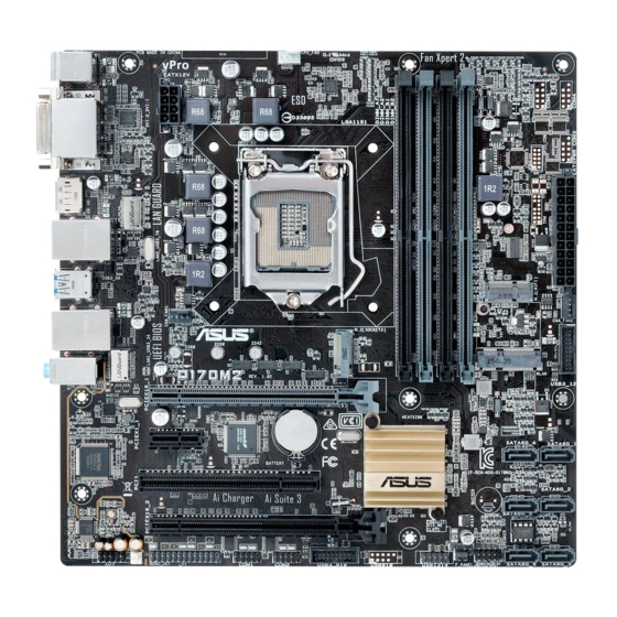
Page 10: Motherboard Layout
Place this side towards the rear of the chassis Q170M2 1.2.3 Motherboard layout 24.4cm(9.6in) KBMS CPU_FAN DIGI +VRM 1442K 1442K EATX12V LGA1151 LAN2_USB3_78 Realtek 8111H M.2(WIFI) USB3_56 CHA_FAN1 CHA_FAN2 LAN1_USB3_34 WLAN 2280 2260 2242 AUDIO Q170M2 USB3_12 PCIEX16_1 Intel I219LM... -
Page 11: Central Processing Unit (Cpu)
1-12 14. Intel ME jumper (3-pin DIS_ME) 1-13 ® 15. USB 2.0 connector (10-1 pin USB1314) 1-20 16. Serial port connectors (10-1 pin COM1, COM2) 1-17 17. LPT connector (26-1 pin LPT) 1-16 18. Mono out header (2-pin MONO_OUT) 1-12 19. Front panel audio connector (10-1 pin AAFP) 1-17 Central Processing Unit (CPU) This motherboard comes with a surface mount LGA1151 socket designed for the 6th Generation Intel Core™ i7 / Core™ i5 / Core™ i3, Pentium and Celeron processors. ® ® ® Q170M2 Q170M2 CPU socket LGA1151 ASUS Q170M2... -
Page 12: Installing The Cpu
Unplug all power cables before installing the CPU. • Ensure that you install the correct CPU designed for the LGA1151 socket only. DO NOT install a CPU designed for LGA1150, LGA1155 and LGA1156 sockets on the LGA1151 socket. • Upon purchase of the motherboard, ensure that the PnP cap is on the socket and the socket contacts are not bent. Contact your retailer immediately if the PnP cap is missing, or if you see any damage to the PnP cap/socket contacts/motherboard components. • Keep the cap after installing the motherboard. ASUS will process Return Merchandise Authorization (RMA) requests only if the motherboard comes with the cap on the LGA1151 socket. • The product warranty does not cover damage to the socket contacts resulting from incorrect CPU installation/removal, or misplacement/loss/incorrect removal of the PnP cap. 1.3.1 Installing the CPU Chapter 1: Product introduction... -
Page 13: Cpu Heatsink And Fan Assembly Installation
1.3.2 CPU heatsink and fan assembly installation Apply the Thermal Interface Material to the CPU heatsink and CPU before you install the heatsink and fan if necessary. ASUS Q170M2... - Page 14 To install the CPU heatsink and fan assembly To uninstall the CPU heatsink and fan assembly Chapter 1: Product introduction...
-
Page 15: System Memory
System memory 1.4.1 Overview This motherboard comes with four Double Data Rate 4 (DDR4) Dual Inline Memory Module (DIMM) sockets. A DDR4 module is notched differently from a DDR, DDR2, or DDR3 module. DO NOT install a DDR, DDR2, or DDR3 memory module to the DDR4 slot. According to Intel CPU spec, DIMM voltage below 1.35 V is recommended to protect the ® CPU. Channel Sockets Channel A DIMM_A1 & DIMM_A2 Channel B DIMM_B1 & DIMM_B2 Q170M2 Q170M2 288-pin DDR4 DIMM sockets 1.4.2 Memory configurations You may install 2 GB, 4 GB, 8 GB and 16 GB unbuffered non-ECC DDR4 DIMMs into the DIMM sockets. You can refer to the recommended memory population below. Recommended memory configurations ASUS Q170M2... - Page 16 ® I nstall a 64-bit Windows OS if you want to install 4GB or more on the ® motherboard. F or more details, refer to the Microsoft support site at http://support.microsoft. ® com/kb/929605/en-us. • The default memory operation frequency is dependent on its Serial Presence Detect (SPD), which is the standard way of accessing information from a memory module. Under the default state, some memory modules for overclocking may operate at a lower frequency than the vendor-marked value. To operate at the vendor-marked or at a higher frequency, refer to section 2.5 Ai Tweaker menu for manual memory frequency adjustment. • Always install the DIMMs with the same CAS Latency. For an optimum compatibility, we recommend that you install memory modules of the same version or data code (D/C) from the same vendor. Check with the vendor to get the correct memory modules. • For system stability, use a more efficient memory cooling system to support a full memory load (4 DIMMs) or overclocking condition. Visit the ASUS website at www.asus.com for the latest QVL. Chapter 1: Product introduction...
- Page 17 1.4.3 Installing a DIMM 1.4.4 Removing a DIMM ASUS Q170M2...
-
Page 18: Expansion Slots
Expansion slots In the future, you may need to install expansion cards. The following sub-sections describe the slots and the expansion cards that they support. Unplug the power cord before adding or removing expansion cards. Failure to do so may cause you physical injury and damage motherboard components. 1.5.1 Installing an expansion card To install an expansion card: Before installing the expansion card, read the documentation that came with it and make the necessary hardware settings for the card. Remove the system unit cover (if your motherboard is already installed in a chassis). -
Page 19: Irq Assignments For This Motherboard
Realtek 8111H – – – shared – – – – controller USB 3.0 Controller shared – – – – – – – SATA Controller shared – – – – – – – HD Audio shared – – – – – – – ASUS Q170M2 1-11... -
Page 20: Headers And Jumpers
Headers and Jumpers Clear RTC RAM (2-pin CLRTC) This header allows you to clear the Real Time Clock (RTC) RAM in CMOS. You can clear the CMOS memory of date, time, and system setup parameters by erasing the CMOS RTC RAM data. The onboard button cell battery powers the RAM data in CMOS, which include system setup information such as system passwords. CLRTC Q170M2 PIN 1 Q170M2 Clear RTC RAM To erase the RTC RAM: Turn OFF the computer and unplug the power cord. Use a metal object such as a screwdriver to short the two pins. Plug the power cord and turn ON the computer. Hold down the <Del> key during the boot process and enter BIOS setup to re- enter data. • If the steps above do not help, remove the onboard battery and short the two pins again to clear the CMOS RTC RAM data. After clearing the CMOS, reinstall the battery. • You do not need to clear the RTC when the system hangs due to overclocking. For system failure due to overclocking, use the CPU Parameter Recall (C.P.R.) feature. Shut down and reboot the system, then the BIOS automatically resets parameter settings to default values. - Page 21 The chassis intrusion sensor or switch sends a high-level signal to this connector when a chassis component is removed or replaced. The signal is then generated as a chassis intrusion event. The chassis intrusion detection feature is disabled by default. To enable it, set the Chassis Intrude Detect Support item in the BIOS to [On]. See section 2.7 Monitor menu in chapter 2 of this user manual for details. CHASSIS Q170M2 Q170M2 Chassis intrusion connector Intel ME jumper (3-pin DIS_ME) ® This jumper allows you to enable or disable the Intel ME function. Set this jumper to ® pins 1-2 to enable (default) the Intel ME function and to pins 2-3 to disable it.
-
Page 22: Connectors
Connectors 1.7.1 Rear panel connectors PS/2 mouse port (green). This port is for a PS/2 mouse. DVI-D port. This port is for any DVI-D compatible device. DVI-D can’t be converted to output RGB Signal to CRT and isn’t compatible with DVI-I. LAN (RJ-45) ports. These ports allow Gigabit connection to a Local Area Network (LAN) through a network hub. LAN port LED indications Activity/Link LED Speed LED Speed Activity Link Status Description Status Description No link 10Mbps connection Orange Linked ORANGE 100Mbps connection Orange Data activity GREEN 1Gbps connection (Blinking) - Page 23 Lime (Rear panel) Line Out Front Speaker Out Front Speaker Out Front Speaker Out Pink (Rear panel) Mic In Mic In Bass/Center Bass/Center Lime (Front panel) Side Speaker Out To configure a 7.1-channel audio output: Use a chassis with HD audio module in the front panel to support a 7.1-channel audio output. USB 3.0 ports. These 9-pin Universal Serial Bus (USB) ports are for USB 3.0 devices. • USB 3.0 devices can only be used for data storage. • We strongly recommend that you connect USB 3.0 devices to USB 3.0 ports for faster and better performance from your USB 3.0 devices. • Due to the design of the Intel 100 series chipset, all USB devices connected to the ® USB 2.0 and USB 3.0 ports are controlled by the xHCI controller. Some legacy USB devices must update their firmware for better compatibility. DisplayPort. This port is for a DisplayPort-compatible devices. DVI-I port. This port is for any DVI-I compatible device and are HDCP compliant, allowing playback of HD DVD, Blu-Ray and other protected content. PS/2 keyboard port (purple). This port is for a PS/2 keyboard. ASUS Q170M2 1-15...
-
Page 24: Internal Connectors
1.7.2 Internal connectors LPT connector (26-1 pin LPT) The LPT (Line Printing Terminal) connector supports devices such as a printer. LPT standardizes as IEEE 1284, which is the parallel port interface on IBM PC-compatible computers. PIN 1 Q170M2 Q170M2 Parallel port connector The LPT module is purchased separately. Mini PCIe slot This slot allows you to install a mini PCIe module into your motherboard. WLAN Q170M2 Q170M2 Mini PCIe slot The mini PCIe module is purchased separately. 1-16 Chapter 1: Product introduction... - Page 25 Front panel audio connector (10-1 pin AAFP) This connector is for a chassis-mounted front panel audio I/O module that supports HD Audio. Connect one end of the front panel audio I/O module cable to this connector. AAFP PIN 1 PIN 1 Q170M2 HD-audio-compliant Legacy AC’97 pin definition compliant definition Q170M2 Front panel audio connector We recommend that you connect a high-definition front panel audio module to this connector to avail of the motherboard’s high-definition audio capability. Serial port connectors (10-1 pin COM1, COM2) These connectors are for serial (COM) ports. Connect the serial port module cable to these connectors, then install the module to a slot opening at the back of the system chassis. COM1 COM2 PIN 1 PIN 1...
- Page 26 CHA FAN IN CHA FAN PWR CHA_FAN1 Q170M2 Q170M2 Fan connectors Do not forget to connect the fan cables to the fan connectors. Insufficient air flow inside the system may damage the motherboard components. These are not jumpers! Do not place jumper caps on the fan connectors! The CPU_FAN connector supports a CPU fan of maximum 1A (12 W) fan power. Speaker connector (4-pin SPEAKER) The 4-pin connector is for the chassis-mounted system warning speaker. The speaker allows you hear system beeps and warnings. SPEAKER Q170M2 PIN 1 Q170M2 Speaker out connector 1-18 Chapter 1: Product introduction...
- Page 27 Q170 Serial ATA 6.0Gb/s connectors (7-pin SATA6G_1~6) ® These connectors connect to Serial ATA 6.0 Gb/s hard disk drives via Serial ATA 6.0 Gb/s signal cables. SATA6G_4 SATA6G_1 SATA6G_5 SATA6G_2 SATA6G_6 SATA6G_3 Q170M2 Q170M2 Intel SATA 6 Gb/s connectors ® When using hot-plug and NCQ, set the SATA Mode Selection item in the BIOS to [AHCI]. M.2 socket 3 This socket allows you to install an M.2 (NGFF) SSD module. M.2(SOCKET3) Q170M2 2280 2260 2242 Q170M2 M.2(SOCKET3)
- Page 28 IntA_P2_SSTX+ IntA_P1_D- PIN 1 IntA_P2_D- IntA_P1_D+ Q170M2 IntA_P2_D+ Q170M2 USB3.0 Front panel connectors The USB 3.0 module is purchased separately. USB 2.0 connector (10-1 pin USB1314) This connector is for USB 2.0 ports. Connect the USB module cable to this connector, then install the module to a slot opening at the back of the system chassis. This USB connector complies with USB 2.0 specifications and supports up to 480Mbps connection speed.
-
Page 29: System Panel Connector
System panel connector (10-1 pin F_PANEL) This connector supports several chassis-mounted functions. F_PANEL +PWR LED- PWR BTN PIN 1 Q170M2 +HDD_LED- RESET Q170M2 System panel connector • System power LED (2-pin PWR_LED) This 2-pin connector is for the system power LED. Connect the chassis power LED cable to this connector. The system power LED lights up when you turn on the system power, and blinks when the system is in sleep mode. • Hard disk drive activity LED (2-pin HDD_LED) This 2-pin connector is for the HDD Activity LED. Connect the HDD Activity LED cable to this connector. The HDD LED lights up or flashes when data is read from or written to the HDD. • ATX power button/soft-off button (2-pin PWR_BTN) This connector is for the system power button. - Page 30 +5 Volts Power OK -5 Volts +5 Volts +5 Volts PSON# Q170M2 +3 Volts -12 Volts +3 Volts +3 Volts PIN 1 Q170M2 ATX power connectors • We recommend that you use an ATX 12V Specification 2.0-compliant or later version power supply unit (PSU) with a minimum of 350W power rating. This PSU type has 24-pin and 4-pin power plugs. • DO NOT forget to connect the 4-pin / 8-pin ATX +12V power plug. Otherwise, the system will not boot up. • We recommend that you use a PSU with higher power output when configuring a system with more power-consuming devices or when you intend to install additional devices. The system may become unstable or may not boot up if the power is inadequate.
-
Page 31: Software Support
To run the Support DVD Place the Support DVD into the optical drive. If Autorun is enabled in your computer, the DVD automatically displays the Specials screen which lists the unique features of your ASUS motherboard. Click Drivers, Utilities, Manual and Special tabs to display their respective menus. The following screen is for reference only. Click to install Click an icon Tick an item and click Install to display to install it a tab If Autorun is NOT enabled in your computer, browse the contents of the Support DVD to locate the file ASSETUP.EXE from the BIN folder. Double-click the ASSETUP.EXE to run the DVD. ASUS Q170M2 1-23... -
Page 32: Sba Support
• PCH with 6th-generation Intel Core™ processor (100 series platforms) with 6.5MB ® Intel Management Engine (ME) 11.0 firmware installed ® CPU and chipsets requirements: * Intel Core™ i3 / i5 /i7 with one of these chipsets: B150, H170, Q170 ® • The Intel Management Engine software kit must be installed (The Local Manageability ® Service and the Intel Management Engine Interface must be installed and running.) ® • Local Administrator rights are required on the target machine. • ® Some models without the 6.5MB Intel Management Engine firmware do not support ® Intel SBA. Please refer to the specification sheet for details. • Visit the ASUS website at www.asus.com for the latest CPU QVL (Qualified Vendors List). • Uninstall SBA3.1 before you install and upgrade to SBA4.0 or latest version. 1-24 Chapter 1: Product introduction... - Page 33 Method 1: Using SATA ODD & USB devices Load USB 3.0 drivers using the ASUS support DVD and install Windows 7 using a USB ® device. Requirement: • 1 x ASUS support DVD • 1 x Windows 7 installation source ® • 1 x SATA ODD • 1 x USB device (ODD or storage) • The USB storage device requires 8 GB or more capacity. It is recommended to format the storage device before use. • ® Use both a USB ODD and a SATA ODD if you want to install Windows 7 64-bit UEFI mode. Insert the Windows 7 installation DVD into a USB ODD, or copy all files on the ® Windows 7 installation DVD to a USB storage device on a working system. ® Connect the USB ODD or USB storage device to your 100 series platform. Insert the ASUS support DVD into a SATA ODD on your 100 series platform. Power on your system and press F8 during POST (Power-On Self Test) to enter the boot screen. ASUS Q170M2 1-25...
- Page 34 Select the USB ODD or USB storage device as the boot device. The USB 3.0 driver will be loaded automatically during installation startup. The “Setup is starting...” screen will show up if the USB 3.0 driver is loaded correctly. Follow the onscreen instructions to complete the Windows 7 installation. ® 1-26 Chapter 1: Product introduction...
- Page 35 ® Requirement: • 1 x ASUS support DVD • 1 x Windows 7 installation source ® • 1 x Working system (PC or notebook) • 1 x SATA ODD On your working system, create an ISO image file of the Windows 7 installation ® source using a third-party ISO software. Copy both “Auto_Unattend.xml” and “Auto_Unattend” folder from the root directory of the ASUS supporting DVD to your system. Edit the ISO file and add both “Auto_Unattend.xml” and “Auto_Unattend” folder into the ISO file. Burn this ISO file onto an empty DVD to create a modified Windows 7 installation ® DVD. Insert the modified Windows 7 installation DVD into an ODD on your 100 series ® platform. Power on your system and press F8 during POST (Power-On Self Test) to enter the boot screen. Select the ODD as the boot device. The USB 3.0 driver will be loaded automatically during installation startup. The “Setup is starting...” screen will show up if the USB 3.0 driver is loaded correctly. Follow the onscreen instructions to complete the Windows 7 installation. ® ASUS Q170M2 1-27...
- Page 36 Method 3: Using ASUS EZ Installer Use the ASUS EZ Installer to create a modified Windows 7 installation source. ® Requirement: • 1 x ASUS support DVD • 1 x Windows 7 installation DVD ® • 1 x Working system (PC or notebook) • 1 x SATA ODD • 1 x USB storage device (8 GB or more) Insert the Windows 7 installation DVD. ® Launch the ASUS EZ Installer located on the ASUS support DVD. Select a method of creating a modified Windows 7 installation file: ® • Windows 7 OS disk to USB storage device ® - Select Windows 7 OS disk to USB storage device then click Next. - Check I agree and then click Next.
- Page 37 - Select the source of the Windows 7 installation disk then click Next. ® - Select the USB storage device and click next. Click the refresh icon if the USB storage device is not displayed. - C lick Yes to clear the contents on the USB storage device and create a bootable USB device. Make sure to backup contents on the USB storage device, as it will be formatted. - Once completed, click OK to finish. ASUS Q170M2 1-29...
- Page 38 • Windows 7 OS disk to ISO file ® ® Before using this method to install Windows • If you are using only one SATA HDD, ensure that your SATA HDD has more than twice the storage space (ISO file size +500MB). • If you are using two or more SATA HDDs, ensure that at least two of your SATA HDDs have more than the storage space (ISO file size +500Mb). - Select Windows 7 OS disk to ISO file then click Next. - Check I agree and then click Next. - Select the source of the Windows 7 installation disk then click Next. ® 1-30 Chapter 1: Product introduction...
- Page 39 - S elect the folder to save the modified Windows 7 installation ISO file and click ® Next. - Once completed, click OK to finish. - B urn this ISO file onto an empty DVD to create a modified Windows ® installation DVD. Insert the modified Windows 7 installation DVD into an ODD or connect the USB ® storage device with modified Windows 7 installation files onto your 100 series ® platform. Power on your system and press F8 during POST (Power-On Self Test) to enter the boot screen. Select the ODD or USB storage device as the boot device. The USB 3.0 driver will be loaded automatically during installation startup. The “Setup is starting...” screen will show up if the USB 3.0 driver is loaded correctly. Follow the onscreen instructions to complete the Windows 7 installation. ® ASUS Q170M2 1-31...
- Page 40 1-32 Chapter 1: Product introduction...
-
Page 41: Chapter 2: Bios Information
Managing and updating your BIOS Save a copy of the original motherboard BIOS file to a USB flash disk in case you need to restore the BIOS in the future. Copy the original motherboard BIOS using the ASUS Update utility. -
Page 42: Asus Ez Flash
2.1.2 ASUS EZ Flash 3 The ASUS EZ Flash 3 feature allows you to update the BIOS without using an OS‑based utility. • Ensure to load the BIOS default settings to ensure system compatibility and stability. Select the Load Optimized Defaults item under the Exit menu. See section 2.10 Exit Menu for details. -
Page 43: Asus Crashfree Bios 3 Utility
2.1.3 ASUS CrashFree BIOS 3 utility The ASUS CrashFree BIOS 3 is an auto recovery tool that allows you to restore the BIOS file when it fails or gets corrupted during the updating process. You can restore a corrupted BIOS file using the motherboard support DVD or a USB flash drive that contains the updated BIOS file. - Page 44 • Turn off the computer. • Ensure that your computer has a DVD optical drive. Booting the system in DOS environment To boot the system in DOS: Insert the USB flash drive with the latest BIOS file and BIOS Updater to the USB port. Boot your computer then press <F8>...
- Page 45 DO NOT shut down or reset the system while updating the BIOS to prevent system boot failaure. Ensure to load the BIOS default settings to ensure system compatibility and stability. Select the Load Optimized Defaults item under the Exit BIOS menu. See section 2.10 Exit Menu for details. ASUS Q170M2 2‑5...
-
Page 46: Bios Setup Program
The BIOS setup screens shown in this section are for reference purposes only, and may not exactly match what you see on your screen. Visit the ASUS website at www.asus.com to download the latest BIOS file for this • motherboard. - Page 47 Selects the boot resets the device priority system Displays the Loads optimized default Advanced mode settings menus The boot device options vary depending on the devices you installed to the system. ASUS Q170M2 2‑7...
-
Page 48: Advanced Mode
2.2.2 Advanced Mode The Advanced Mode provides advanced options for experienced end‑users to configure the BIOS settings. The figure below shows an example of the Advanced Mode. Refer to the following sections for the detailed configurations. To access the EZ Mode, click EzMode(F7) or press <F7>. MyFavorite Q-Fan Quick... -
Page 49: Menu Items
A scroll bar appears on the right side of a menu screen when there are items that do not fit on the screen. Press the Up/Down arrow keys or <Page Up> / <Page Down> keys to display the other items on the screen. ASUS Q170M2... -
Page 50: General Help
General help At the top right corner of the menu screen is a brief description of the selected item. Use <F12> key to capture the BIOS screen and save it to the removable storage device. Configuration fields These fields show the values for the menu items. If an item is user‑configurable, you can change the value of the field opposite the item. - Page 51 To configure your fans: Select the fan that you want to configure and to view its current status. Click and drag the speed points to adjust the fans’ operating speed. Click Apply to save the changes then click Exit (ESC). ASUS Q170M2 2-11...
-
Page 52: Ez Tuning Wizard
2.2.4 EZ Tuning Wizard EZ Tuning Wizard allows you to view your CPU and DRAM, computer usage, and CPU fan settings. You can also easily set RAID in your system using this feature. Tuning your system settings To tune your settings: Press <F11>... -
Page 53: Creating Raid
Ensure that your HDDs have no existing RAID volumes. • Ensure to connect your HDDs to Intel SATA connectors. ® The available HDDs display. Click Next to continue. Select the type of storage for your RAID Easy Backup or Super Speed, then click Next. ASUS Q170M2 2‑13... - Page 54 For Easy Backup, select from Easy Backup (RAID1) or Easy Backup (RAID10) then click Next. You can only select Easy Backup (RAID 10) if you connect four (4) HDDs. For Easy Backup, select from Super Speed (RAID0) or Super Speed (RAID5) then click Next.
-
Page 55: My Favorites
My Favorites MyFavorites is your personal space where you can easily save and access your favorite BIOS items. ASUS Q170M2 2‑15... - Page 56 Adding items to My Favorites To add BIOS items: Press <F3> on your keyboard or click from the BIOS screen to open Setup Tree Map screen. On the Setup Tree Map screen, select the BIOS items that you want to save in MyFavorites screen.
-
Page 57: Main Menu
RAM to clear the BIOS password. See section 1.6 Headers and Jumpers for information on how to erase the RTC RAM. The Administrator or User Password items on top of the screen show the default • Not Installed. After you set a password, these items show Installed. ASUS Q170M2 2‑17... -
Page 58: Administrator Password
Administrator Password If you have set an administrator password, we recommend that you enter the administrator password for accessing the system. To set an administrator password: Select the Administrator Password item and press <Enter>. From the Create New Password box, key in a password, then press <Enter>. From the Confirm New Password box, key in your password again to confirm the password, then click OK. -
Page 59: Ai Tweaker Menu
When the CPU Core Ratio is set to [Sync All Cores] or [Per Core], the following items appear: 1-Core Ratio Limit [Auto] Select [Auto] to apply the CPU default Turbo Ratio setting or manually assign a 1‑Core Limit value that must be higher than or equal to the 2‑Core Ratio Limit. ASUS Q170M2 2-19... - Page 60 EPU Power Saving Mode [Disabled] ASUS EPU (Energy Processing Unit) sets the CPU in its minimum power consumption settings. Enable this item to set lower CPU VCCIN and Vcore voltages and achieve the best energy saving condition.
-
Page 61: Dram Timing Control
Fixed CPU VRM Switching Frequency (KHz) [250] This item allows you to set a higher frequency for a quicker transient response speed. Use the <+> and <‑> keys to adjust the value. The values range from 250KHz to 500KHz with a 50KHz interval. ASUS Q170M2 2-21... - Page 62 CPU Power Duty Control [T.Probe] DIGI + VRM Duty control adjusts the current and thermal conditions of every component’s phase. [T. Probe] Select to maintain the VRM thermal balance. [Extreme] Select to maintain the current VRM balance. CPU Power Phase Control [Auto] This item allows you to set the power phase control of the CPU.
- Page 63 Allows you to limit the DC Loadline in 1/100 mOhms. Use <+> and <‑> key to adjust the value. CPU Core/Cache Current Limit Max. [Auto] Allows you to configure a higher current limit to prevent a frequency or power throttling when overclocking. The values range from 0.00A to 255.50A with a 0.25A interval. ASUS Q170M2 2‑23...
- Page 64 CPU Graphics Current Limit Max. [Auto] Allows you to configure a higher current limit to prevent a frequency or power throttling when overclocking. The values range from 0.00A to 255.50A with a 0.25A interval. Min. CPU Cache Ratio [Auto] Allows you to configure the minimum possible CPU cache ratio. Use the <+> or <‑> keys to adjust the value.
- Page 65 DRAM DATA REF Voltage on CHA DIMM0 Rank1 BL0-7 [Auto] Configures the DRAM Data REF Voltage. Configuration options: [Auto] [0] ‑ [63] DRAM DATA REF Voltage on CHA DIMM1 Rank0 BL0-7 [Auto] Configures the DRAM Data REF Voltage. Configuration options: [Auto] [0] ‑ [63] ASUS Q170M2 2‑25...
- Page 66 DRAM DATA REF Voltage on CHA DIMM1 Rank1 BL0-7 [Auto] Configures the DRAM Data REF Voltage. Configuration options: [Auto] [0] ‑ [63] DRAM DATA REF Voltage on CHB DIMM0 Rank0 BL0-7 [Auto] Configures the DRAM Data REF Voltage. Configuration options: [Auto] [0] ‑ [63] DRAM DATA REF Voltage on CHB DIMM0 Rank1 BL0-7 [Auto] Configures the DRAM Data REF Voltage.
-
Page 67: Advanced Menu
Only one thread per activated core is enabled. Active Processor Cores [All] This item allows you to select the number of CPU cores to activate in each processor package. Configuration options: [All] [1] [2] [3] For some CPU types, only [All] and [1] appear. ASUS Q170M2 2‑27... -
Page 68: Cpu Power Management Configuration
Intel Virtualization Technology [Disabled] When set to [Enabled], a VMM can utilize the additional hardware capabilities provided by Vanderpool Technology. Configuration options: [Disabled] [Enabled] Hardware Prefetcher [Enabled] This item allows you to turn on/off the MLC streamer prefetcher. Configuration options: [Disabled] [Enabled] Adjacent Cache Line Prefetcher [Enabled] This item allows you to turn on/off prefetching adjacent cache lines. -
Page 69: Platform Misc Configuration
ASPM to take effect. Configuration options: [Disabled] [L1] PEG-ASPM [Disabled] This item allows you to select the ASPM state for energy‑saving conditions, or use the ASUS optimized energy saving profile. Configuration options: [Disabled] [Auto] [ASPM L0s] [ASPM... -
Page 70: Amt Configuration
AMT Configuration The items in this menu allow you to change the Intel Active Management Technology (AMT) ® feature. Intel AMT [Enabled] ® Allow you to enable or disable the Intel Active Management Technology (AMT) in the BIOS ® extension. Configuration options: [Enabled] [Disabled] •... -
Page 71: Memory Configuration
SATA Port items show Empty if no SATA device is installed to the corresponding SATA port. Hyper Kit Mode [Disabled] Disables this option for M.2 devices. Enables this option for ASUS Hyper Kit card. Configuration options: [Disabled] [Enabled] SATA Controller(s) [Enabled] Enables or disables onboard the SATA device. -
Page 72: Usb Configuration
SATA Mode Selection [AHCI] Allows you to set the SATA configuration. [AHCI] Set to [AHCI] when you want the SATA hard disk drives to use the AHCI (Advanced Host Controller Interface). The AHCI allows the onboard storage driver to enable advanced Serial ATA features that increases storage performance on random workloads by allowing the drive to internally optimize the order of commands. -
Page 73: Onboard Devices Configuration
This item appears only when you set the previous item to [On] and allows you to enable or disable the PXE OptionRom of the Realtek LAN controller. Configuration options: [On] [Off] Intel LAN Controller [Enabled] [Enabled] Enables the Intel LAN controller. [Disabled] Disables the controller. ASUS Q170M2 2‑33... -
Page 74: Serial Port Configuration
Intel PXE Option ROM [Off] This item appears only when you set the previous item to [Enabled] and allows you to enable or disable the PXE Option ROM of the Intel LAN controller. Configuration options: [Off] [On] Charging USB devices in Power State S5 [Disabled] [Enabled] Charges USB devices even when the system is in Power State S5. -
Page 75: Apm Configuration
VT‑UTF8 is the preferred terminal type for out‑of‑band management. The next best choice is VT100+ and then VT100. Configuration options: [VT100] [VT100+] [VT‑UTF8] [ANSI] Bits per second [115200] Allows you to select the transmission speed of the serial port. Configuration options: [9600] [19200] [38400] [57600] [115200] ASUS Q170M2 2‑35... - Page 76 Data Bits [7] Allows you to select the data bits. Configuration options: [7] [8] Parity [None] A parity bit can be sent with the data bits to detect some transmission errors. This item allows you to set the parity bit. Configuration options: [None] [Even] [Odd] [Mark] [Space] Stop Bits [1] Stop bits indicate the end of a serial data packet.
-
Page 77: Network Stack Configuration
This item allows user to disable or enable the Ipv6 PXE Boot support. Configuration options: [Disabled] [Enabled] Intel TXT Information This menu displays the Intel TXT information. HDD/SSD SMART Information This menu displays the SMART information of the connected devices. ASUS Q170M2 2‑37... -
Page 78: Monitor Menu
Monitor menu The Monitor menu displays the system temperature/power status, and allows you to change the fan settings. Scroll down to display more items. CPU / MotherBoard Temperature [xxxºC/xxxºF] The onboard hardware monitor automatically detects and displays the CPU / motherboard temperatures. - Page 79 Use the <+> and <‑> keys to adjust the minimum CPU fan duty cycle. The values range from 20% to 100%. When the CPU temperature is under the lower limit, the CPU fan will operate at the minimum duty cycle. ASUS Q170M2 2‑39...
- Page 80 Chassis1/2 Q-Fan Control [Enabled] [PWM mode] Enables the chassis Q‑Fan control in PWM mode for 4‑pin chassis fan. [DC mode] Enables the chassis Q‑Fan control in DC mode for 3‑pin chassis fan. [Disabled] Disables the chassis Q‑Fan control feature. The following items appear only when you set the Chassis Fan 1/2 Q‑Fan Control to [PWM Mode] or [DC Mode].
-
Page 81: Boot Menu
The following six items appear when you set Fast Boot to [Enabled]. Next Boot after AC Power Loss [Normal Boot] [Normal Boot] Returns to normal boot on the next boot after AC power loss. [Fast Boot] Accelerates the boot speed on the next boot after AC power loss. ASUS Q170M2 2-41... - Page 82 Boot Logo Display [Auto] [Auto] Adjust automatically for Windows® requirement. [Full Screen] Maximize the boot logo size. [Disabled] Hide the logo during POST. POST Delay Time [3 sec] This item appears only when you set Boot Logo Display to [Enabled]. This item allows you to select the desired additional POST waiting time to easily enter the BIOS setup.
-
Page 83: Secure Boot
This item allows you to immediately load the default Security Boot keys, Platform key (PK), Key‑exchange Key (KEK), Signature database (db), and Revoked Signatures (dbx). When the default Secure boot keys are loaded, all the Secure Boot keys’ state will change from Unloaded mode to loaded mode. ASUS Q170M2 2‑43... - Page 84 Clear Secure Boot keys This item appears only when you load the default Secure Boot keys. This item allows you to clear all the previously applied Secure Boot keys. Save Secure Boot Keys This item allows you to save all the Secure Boot keys to a USB storage device. PK Management The Platform Key (PK) locks and secures the firmware from any non‑permissible changes.
-
Page 85: Boot Option Priorities
• To select the boot device during system startup, press <F8> when ASUS Logo appears. • To access Windows OS in Safe Mode, do any of the following: •... -
Page 86: Tool Menu
<Enter> to display the submenu. ASUS EZ Flash 3 Utility Allows you to run ASUS EZ Flash 3. Press [Enter] to launch the ASUS EZ Flash 3 screen. For more details, see section 2.1.2 ASUS EZ Flash 3. Setup Animator [Disabled] This item allows you to enable or disable the Setup animator. -
Page 87: Exit Menu
<Esc>, a confirmation window appears. Select Yes to discard changes and exit. Launch EFI Shell from USB drives This option allows you to attempt to launch the EFI Shell application (shellx64.efi) from one of the available USB devices. ASUS Q170M2 2‑47... - Page 88 2‑48 Chapter 2: Getting started...
-
Page 89: Appendices
Consult the dealer or an experienced radio/TV technician for help. The use of shielded cables for connection of the monitor to the graphics card is required to assure compliance with FCC regulations. Changes or modifications to this unit not expressly approved by the party responsible for compliance could void the user’s authority to operate this equipment. Q170M2... -
Page 90: Canadian Department Of Communications Statement
IC: Canadian Compliance Statement Complies with the Canadian ICES-003 Class B specifications. This device complies with RSS 210 of Industry Canada. This Class B device meets all the requirements of the Canadian interference-causing equipment regulations. This device complies with Industry Canada license exempt RSS standard(s). Operation is subject to the following two conditions: (1) this device may not cause interference, and (2) this device must accept any interference, including interference that may cause undesired operation of the device. - Page 91 ASUS Recycling/Takeback Services ASUS recycling and takeback programs come from our commitment to the highest standards for protecting our environment. We believe in providing solutions for you to be able to responsibly recycle our products, batteries, other components as well as the packaging materials.
- Page 92 Slovenščina AsusTek Inc. tukaj izjavlja, da je ta naprava skladna s di conformità CE. temeljnimi zahtevami in drugimi relevantnimi določili direktiv CE. Za več Русский Компания ASUS заявляет, что это устройство соответствует informacij glejte Izjavo CE o skladnosti. основным требованиям и другим соответствующим условиям...
-
Page 93: Asus Contact Information
+1-510-739-3777 +1-510-608-4555 Web site http://www.asus.com/us/ Technical Support Support fax +1-812-284-0883 Telephone +1-812-282-2787 Online support http://qr.asus.com/techserv ASUS COMPUTER GmbH (Germany and Austria) Address Harkort Str. 21-23, D-40880 Ratingen, Germany +49-2102-959931 Web site http://www.asus.com/de Online contact http://eu-rma.asus.com/sales Technical Support Telephone +49-2102-5789555 Support Fax... - Page 94 Appendices...
Need help?
Do you have a question about the Q170M2 and is the answer not in the manual?
Questions and answers