Table of Contents
Advertisement
Advertisement
Table of Contents

Related Manuals for thomann Harley Benton DNAfx GiT Pro


Summary of Contents for thomann Harley Benton DNAfx GiT Pro
- Page 1 DNAfx GiT Pro multi effects unit user manual...
- Page 2 Thomann GmbH Hans-Thomann-Straße 1 96138 Burgebrach Germany Telephone: +49 (0) 9546 9223-0 Internet: www.thomann.de 11.01.2022, ID: 517099...
-
Page 3: Table Of Contents
Table of contents Table of contents General information..........................5 1.1 Further information........................... 6 1.2 Notational conventions........................7 1.3 Symbols and signal words....................... 9 Safety instructions..........................10 Features............................... 12 Installation..............................14 4.1 Connection options......................... 15 Connections and operating elements................... 24 Operating..............................29 6.1 Presets.............................. - Page 4 Table of contents 6.6 Tuner..............................48 6.7 System settings..........................48 6.8 Editor software..........................65 6.9 Software update..........................66 Effects list..............................67 Technical specifications........................84 Plug and pin assignments........................87 Protecting the environment......................90 multi effects unit...
-
Page 5: General Information
Our products and user manuals are subject to a process of continuous development. We there‐ fore reserve the right to make changes without notice. Please refer to the latest version of the user manual which is ready for download under www.thomann.de. DNAfx GiT Pro... -
Page 6: Further Information
General information 1.1 Further information On our website (www.thomann.de) you will find lots of further information and details on the following points: Download This manual is also available as PDF file for you to download. Use the search function in the electronic version to find the topics of Keyword search interest for you quickly. -
Page 7: Notational Conventions
General information 1.2 Notational conventions This manual uses the following notational conventions: Letterings The letterings for connectors and controls are marked by square brackets and italics. Examples: [VOLUME] control, [Mono] button. Displays Texts and values displayed on the device are marked by quotation marks and italics. Examples: ‘24ch’... - Page 8 General information Instructions The individual steps of an instruction are numbered consecutively. The result of a step is indented and highlighted by an arrow. Example: Switch on the device. Press [Auto]. ð Automatic operation is started. Switch off the device. Cross-references References to other locations in this manual are identified by an arrow and the specified page number.
-
Page 9: Symbols And Signal Words
General information 1.3 Symbols and signal words In this section you will find an overview of the meaning of symbols and signal words that are used in this manual. Signal word Meaning DANGER! This combination of symbol and signal word indicates an immediate dangerous situation that will result in death or serious injury if it is not avoided. -
Page 10: Safety Instructions
Safety instructions Safety instructions Intended use This device is intended to be used for sound processing of signals from musical instruments with electromagnetic pickups. Any other use or use under other operating conditions is con‐ sidered to be improper and may result in personal injury or property damage. No liability will be assumed for damages resulting from improper use. - Page 11 Safety instructions NOTICE! Operating conditions This device has been designed for indoor use only. To prevent damage, never expose the device to any liquid or moisture. Avoid direct sunlight, heavy dirt, and strong vibrations. Only operate the device within the ambient conditions specified in the chapter ‘Technical specifications’...
-
Page 12: Features
Features Features Special features of the device: Wide variety of professional Amp Modelings IR cabinet simulations (Impulse Response) for recording and FOH application (max. 30 IR files) can be loaded 153 different guitar effects in 11 effect modules Different high quality digital and analogue effects, even in stereo Selectable order of the effects in the effects chain 3 footswitch control modes Stereo FX Loop for external effects... - Page 13 Features Audio interface for recording and playback via USB Editor software Robust aluminium housing Power adapter supplied DNAfx GiT Pro...
-
Page 14: Installation
Installation Installation Unpack and check carefully there is no transportation damage before using the unit. Keep the equipment packaging. To fully protect the product against vibration, dust and moisture during transportation or storage use the original packaging or your own packaging material suitable for transport or storage, respectively. -
Page 15: Connection Options
Installation 4.1 Connection options Connection to the power supply. NOTICE! External power supply The device is powered by an external power supply. Before connecting the external power supply, ensure that the input voltage (AC outlet) matches the voltage rating of the device and that the AC outlet is protected by a residual cur‐ rent circuit breaker. - Page 16 Installation Connection to the amplifier and the power amp This setup can be used on any amplifier with FX LOOP or individual power amp. OUTPUT L OUTPUT R DC IN MIDI IN/ 9V 1A MIDI OUT AMP CTRL PEDAL 2 INPUT SEND RETURN L...
- Page 17 Installation Connection to the input socket of the amplifier This setup can be used, if the amplifier does not have an FX LOOP. The unit is placed in front of the amplifier. The signal from the unit goes to the preamp of an amplifier. OUTPUT L OUTPUT R DC IN...
- Page 18 Installation Connection to the FX LOOP of an amplifier This setup can be used, if the amplifier has an FX LOOP and the unit is to be used with an amplifier as a post effect. The unit is placed between preamp and power am of the amplifier. OUTPUT L OUTPUT R DC IN...
- Page 19 Installation Disable the effect modules ‘AMP’ and ‘CAB’ for best results. Four-cable method This setup can be used to use the unit as Distortion/Overdrive/Boost pedal in front of the preamp of an amplifier and as Modulation/Delay/Reverb pedal between the preamp and power amp of an amplifier.
- Page 20 Installation Connect the RETURN interface of the amplifier to the output socket (jack) [OUTPUT L] of the unit. Connect the SEND interface of the amplifier to the input socket [RETURN L] of the unit. Connect the input of the amplifier to the output socket [SEND] of the unit. Place the dynamic effects, Rah effects, EQ and Distortion/Overdrive effects before the preamp.
- Page 21 Installation Connection to FRFR device This setup supports studio monitors, audio interfaces, stage monitors, PA systems, head‐ phones or any other FRFR (full range flat response) devices. OUTPUT L OUTPUT R DC IN MIDI IN/ 9V 1A MIDI OUT AMP CTRL PEDAL 2 INPUT SEND...
- Page 22 Installation Connect the headphones to the phones socket. Enable the effect modules ‘AMP’ and ‘CAB’ for best results. Connection to FRFR device and amplifier In this setup, you can connect an FRFR device and an amplifier simultaneously. OUTPUT L OUTPUT R DC IN MIDI IN/ 9V 1A...
- Page 23 Installation Connect the RETURN interface of the amplifier or an individual power amp to the output socket (jack) [OUTPUT L] of the unit. Connect a studio monitor, stage monitor, mixer or other FRFR device to the output socket (jack) [OUTPUT R] or the output socket (XLR) [OUTPUT R] of the unit. For the output with FRFR device, set output mode ‘CAB’...
-
Page 24: Connections And Operating Elements
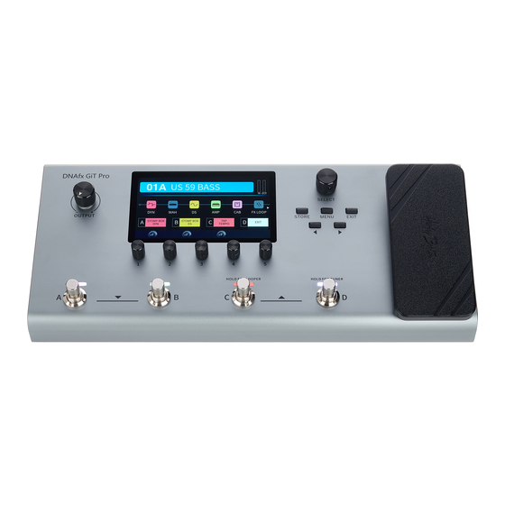
Connections and operating elements Connections and operating elements Top side &' PEDAL ö SELECT OUTPUT STORE MENU EXIT HOLD FOR LOOPER HOLD FOR TUNER multi effects unit... - Page 25 Connections and operating elements 1 [OUTPUT] Rotary volume control 2 Display 3 [STORE] Button to enter save menu 4 [SELECT] Rotary control to switch between preset patches, to select a module in the effects chain, or to navigate in the settings menu 5 [MENU] Button to enter the system settings 6 [EXIT]...
- Page 26 Connections and operating elements Rear panel OUTPUT L OUTPUT R DC IN MIDI IN/ 9V 1A MIDI OUT AMP CTRL PEDAL 2 INPUT SEND RETURN L RETURN R OUTPUT L OUTPUT R AUX IN LIFT . / 0 1 7 8 9 : 12 [AUX IN] 1/8"...
- Page 27 Connections and operating elements 19 Headphone socket (1/8" jack socket, stereo) 20 [LFT] / [GND] Ground/Lift switch for XLR output, balanced 21 [OUTPUT L] / [OUTPUT R] XLR output socket, 3-pin, mono, balanced 22 [MIDI IN/] [MIDI OUT] MIDI socket, 5-pin 23 [USB] USB port type B for connecting the unit to a PC or MAC or a suitable audio device You can edit preset patches or update the firmware via editor software.
- Page 28 Connections and operating elements Display < 26 Preset area Display of number of the current preset bank, preset patch ( ‘A’ , ‘B’ , ‘C’ , ‘D’ ) and the preset name 27 ‘IN’ / ‘OUT’ Displays the current volume level 28 Effects chain area Display of the effects chain of the current preset 29 Parameter area...
-
Page 29: Operating
Operating Operating Turn [OUTPUT] counter-clockwise to set the volume to minimum. Switch on the unit and adjust the volume as required. DNAfx GiT Pro... -
Page 30: Presets
Operating 6.1 Presets 6.1.1 Selecting presets The unit has 64 preset banks, each with 4 preset patches, for 256 preset patches in total. The currently selected preset border will always be highlighted. When the presets are selected, turn [SELECT] to switch between preset patches. You can also press the footswitches [A]…[D] to switch preset patches in the same bank. - Page 31 Operating 6.1.2 Editing presets The unit has 11 effect modules ( ‘DYN’ , ‘WAH’ , ‘DS’ , ‘AMP’ , ‘CAB’ , ‘FX LOOP’ , ‘NS’ , ‘EQ’ , ‘MOD’ , ‘DELAY’ , ‘REVERB’ ) for setting up to 153 effects. Every effect module can only be set once in the effects chain.
- Page 32 Operating Enabling / disabling effect module Turn [SELECT] to select an effect module. ð The icon border of the effect module is highlighted. Press [1] to enable the effect module. ð The effect module is enabled. The relevant icon is coloured. The display shows ‘ON’ in the parameter area.
- Page 33 Operating Editing effects Turn [SELECT] to select an effect module. Turn [1] to select the different effect types. Turn [2]…[5] to adjust the relevant parameters shown in the parameter area. Press [2]…[5] to reset the current parameter to the default setting. If an effect module has more than four parameters, use to scroll to the other parame‐...
- Page 34 Operating You must save a modified preset with [STORE]. 6.1.3 Storing presets The unit supports max. 15 characters for preset names. Press [STORE] to enter save menu. Turn [SELECT] to select a save slot. Turn [1] to switch the position. Turn [2] to select a desired letter for the preset name.
-
Page 35: Footswitch Modes
Operating After naming is complete, press again [STORE] to confirm saving. ð The display shows the home display. Press or turn a control to cancel saving. 6.2 Footswitch modes The unit has three footswitch modes. Press the relevant footswitch [A], [B] or [C] in the current preset patch to enter the foot‐ switch control menu. - Page 36 Operating Mode ‘STOMPBOX’ This mode allows you to assign an effect module to one of the footswitches [A], [B] or [C], with which you can then enable or disable the effect module. By default, the effect modules are dis‐ abled, the footswitch LED is off. Press [1] to select ‘STOMPBOX’...
- Page 37 Operating Mode ‘TAP TEMPO’ This mode allows you to set the delay time using one of the footswitches [A], [B] or [C]. Press [2] to select ‘TAP TEMPO’ . ð In the parameter area is shown ‘TAP TEMPO’ . The background colour is red. The foot‐ switch LED flashes red.
- Page 38 Operating This mode allows you to switch the amplifier channels using one of the footswitches [A], [B] or [C]. Connect the [AMP CTRL] socket of the unit to the footswitch socket of the amplifier using a 1/4" TRS jack cable (stereo). Press [3] to select ‘AMP CTRL’...
-
Page 39: Fx Loop
Operating 6.3 FX LOOP The unit has an FX LOOP which can be used with the four-cable method. Press [SELECT] to enter the editing mode. Turn [SELECT] and select ‘FX LOOP’ . Turn [1] to toggle between serial and parallel mode ( ‘SERIAL’ / ‘PARALLEL’ ). Turn [2] and [3] to adjust the input and output volume level (default setting 0 dB). -
Page 40: Expression Pedal
Operating 6.4 Expression pedal The unit has a native Expression Pedal ( ‘PEDAL1’ ) and supports an external pedal ( ‘PEDAL2’ ) using a 1/4" TRS jack cable (stereo). The LED [1] lights up blue when the native pedal is ena‐ bled. - Page 41 Operating Adjusting the volume When the native Expression Pedal ( ‘PEDAL1’ ) is disabled (LED off), you can use it for adjusting the volume level. Press the pedal to adjust the master output volume level. External pedals cannot be used for adjusting the volume level. Entering the Expression Pedal settings Press and hold [1], [2] and [3] for more than 2 seconds.
- Page 42 Operating Turn [1] in the submenu ‘PEDAL1’ or ‘PEDAL2’ to enable or disable the relevant Expres‐ sion Pedal. Turn [2] or [3] to set the minimum and maximum position of the pedal (toe down / heel down). ð Now you can use the Expression Pedal to set the selected parameter. On the home display, the relevant parameter lights up red.
-
Page 43: Setting 'Looper / Rhythm
Operating 6.5 Setting ‘LOOPER / RHYTHM’ The FX LOOP of the unit supports loops with a length of max. 52 seconds with 8 built-in drum and metronome styles, each style with 10 different grooves. Press and hold the footswitch [C] to enter the ‘LOOPER/RHYTHM’ menu. ‘LOOPER’... - Page 44 Operating Press the footswitch [B] during ‘PLAY’ to stop playback. ð The LED of the footswitch [B] lights up blue. Press and hold the footswitch [B] at any time to clear all the recorded tracks. ð The LED of the footswitch [B] is off. When the looper recorded bar is full (52 seconds), it will stop recording and start play‐...
- Page 45 Operating ‘RHYTHM’ Press the footswitch [C] to enable or disable the drum machine. ð The LED of the footswitch [C] stays white. Press the footswitch [D] repeatedly to adjust the speed of the drum machine via ‘TAP TEMPO’ . ð The LED of the footswitch [D] flashes according to the current speed of the drum machine.
- Page 46 Operating Synchronising ‘LOOPER’ with ‘RHYTHM’ For playing and practicing, you can enable simultaneously ‘LOOPER’ and ‘RHYTHM’ . Syn‐ chronise as follows: Press the footswitch [C] to enable the drum machine. Press the footswitch [A] to start recording. ð The drum machine restarts simultaneously. When the recording is finished, press the footswitch [B] to stop recording and to start the playback.
- Page 47 Operating If the looper is stopped and then started again, the drum machine and the looper will restart rom the beginning simultaneously. In the following situations, the drum machine will synchronise with the looper: Recording a track with the looper before the drum machine. While the looper synchronises with the drum machine, the speed of the drum machine will adapt to the recording.
-
Page 48: Tuner
Operating 6.6 Tuner Press and hold the footswitch [D] for more than 2 seconds. ð The tuner is enabled. Turn [1] to adjust the reference frequency (default value 440 Hz, range: 430 Hz…450 Hz). Turn [2] to select between the modes ‘MUTE’ and ‘BYPASS’ (default setting ‘MUTE’ ). Press any footswitch or [EXIT ] to quit tuner mode. - Page 49 Operating ‘INPUT LEVEL’ Turn [1] to adjust the input volume level. The range is from ‘–6 dB’ … ‘+6 dB’ (default value 0 dB, no gain or attenuation). ‘OUTPUT MODE’ Turn [1] or [2] to enable or disable the cabinet simulation. This setting will affect the balanced outputs and the unbalanced outputs (default setting On) When the settings for the left and the right output are different, the cabinet simulation is placed at the end of the effects chain.
- Page 50 Operating ‘PREAMP SYNC’ This setting decides, if the cabinet simulation synchronises with the ‘AMP’ module. If the func‐ tion is enables, the cabinet simulation synchronises automatically with the ‘AMP’ module when the ‘AMP’ module is changed in the effects chain. The default setting is Off. ‘PEDAL CALIBRATE’...
- Page 51 Operating Press [1] or [2] to confirm and finish the calibration. ð The display shows ‘PEDAL SETTING COMPLETED’ . Calibrate the pedal again, if the display shows ‘PLEASE SET AGAIN’ . ‘TAP TEMPO’ Turn [1] to enter ‘TAP TEMPO’ mode of the delay effect. PRESET The BPM value is stored in the preset patch.
- Page 52 Operating ‘MIDI SETTING’ Turn [1] to toggle between ‘MIDI IN’ and ‘MIDI OUT’ . ð In case of ‘MIDI IN’ (default setting), the unit can be controlled by another device via MIDI signals. In case of ‘MIDI OUT’ , the unit can control another device via MIDI-PC#. Turn [2] to select a MIDI channel (default setting channel 1).
- Page 53 Operating PC Mapping MIDI Bank PC# Preset MIDI Bank PC# Preset MIDI Bank PC# Preset DNAfx GiT Pro...
- Page 54 Operating MIDI Bank PC# Preset MIDI Bank PC# Preset MIDI Bank PC# Preset 14 A 12 A 15 A 10 A 13 A 16 A 11 A multi effects unit...
- Page 55 Operating MIDI Bank PC# Preset MIDI Bank PC# Preset MIDI Bank PC# Preset 17 A 20 A 23 A 18 A 21 A 24 A 19 A 22 A DNAfx GiT Pro...
- Page 56 Operating MIDI Bank PC# Preset MIDI Bank PC# Preset MIDI Bank PC# Preset 25 A 28 A 31 A 26 A 29 A 32 A 27 A 30 A multi effects unit...
- Page 57 Operating MIDI Bank PC# Preset MIDI Bank PC# Preset MIDI Bank PC# Preset 33 A 36 A 39 A 34 A 37 A 40 A 35 A 38 A 41 A DNAfx GiT Pro...
- Page 58 Operating MIDI Bank PC# Preset MIDI Bank PC# Preset MIDI Bank PC# Preset 44 A 47 A 42 A 45 A 48 A 43 A 46 A 49 A multi effects unit...
- Page 59 Operating MIDI Bank PC# Preset MIDI Bank PC# Preset MIDI Bank PC# Preset 55 A 50 A 53 A 56 A 51 A 54 A 57 A 52 A DNAfx GiT Pro...
- Page 60 Operating MIDI Bank PC# Preset MIDI Bank PC# Preset MIDI Bank PC# Preset 58 A 63 A 61 A 59 A 64 A 62 A 60 A multi effects unit...
- Page 61 Operating CC Reference Function Value Function Value MIDI BANK 0…1 DELAY ON/OFF 0…127 DYNAMIC ON/OFF 0…127 REVERB ON/OFF 0…127 WAH ON/OFF 0…127 FOOTSWITCH A 0…127 DS ON/OFF 0…127 FOOTSWITCH B 0…127 AMP ON/OFF 0…127 FOOTSWITCH C 0…127 CAB ON/OFF 0…127 FOOTSWITCH D 0…127 FX LOOP ON/OFF...
- Page 62 Operating Function Value Function Value PLAY 0…127 RHYTHM TAP 0…127 STOP 0…127 PEDAL 1 ON/OFF 0…127 CLEAR 0…127 PEDAL 1 0…127 RHYTHM ON/OFF 0…127 PEDAL 2 0…127 multi effects unit...
- Page 63 The unit can be used as USB audio interface (24 bit, 44.1 kHz) with support for DAWs in Win‐ dows® and MAC. Windows® users have to install ASIO drivers to achieve low-latency recording and monitoring. Refer to www.harleybenton.com or our homepage www.thomann.de to down‐ load the ASIO drivers.
- Page 64 Operating ‘RESET’ Press and hold [1] for more than 2 seconds to confirm the factory reset. When the loading bar finishes, the unit will reboot automatically as the factory reset is completed. The factory reset will delete all user preset patches and loaded IR files. We recommend backing up the presets and IR files before resetting.
-
Page 65: Editor Software
With the dedicated editor software, the unit can be computer-controlled (PC or MAC) for preset editing, preset patch managing, IR files loading, backing up and factory resetting. Refer to www.harleybenton.com or our homepage www.thomann.de to download the free editor software and install it. -
Page 66: Software Update
Operating 6.9 Software update Refer to www.harleybenton.com or our homepage www.thomann.de to download the current software version. Install the current software version on your computer. Press and hold [SELECT] and switch on the device. Connect your computer to the device via the USB socket of the device. -
Page 67: Effects List
Effects list Effects list Dynamic Number Name Template/description GEMSTONE COMP Diamond Comp Jr compressor CS COMP BOSS CS-2 compressor SLOW GEAR Slow attack effect DNAfx GiT Pro... - Page 68 Effects list Number Name Template/description 95 CRY WAH Dunlop GCB95 535 CRY WAH Dunlop Cry Baby 535Q AH WAH Talking Wah AH OH WAH Talking Wah OH AUTO WAH Automatic sweeping Wah DYNAMIC WAH Automatic Wah changes according to the touch pressure on the strings multi effects unit...
- Page 69 Effects list Distortion Number Name Template/description CLEAN BOOST Xotic RC Booster TUBE BOOST Xotic AC Booster 808 SCREAMER Ibanez TS808 overdrive BK DRIVE B.K.Butler Tube Drive overdrive BLACK MOUSE Pro Co Rat distortion DIRECT GAIN Barber Direct Drive overdrive MT ZONE BOSS Metal Zone distortion MT MASTER Digitech Metal Master distortion...
- Page 70 Effects list Number Name Template/description FULL DRIVE Fulltone Full-Drive 2 distortion SHREDDER Marshall Shred Master distortion GOLD TONE Klon Centaur Gold overdrive FULL DIST Fulltone GT-500 distortion PURPLE DIST Suhr Riot distortion TIGHTLY DIST Amptweaker TightRock distortion FAZ FACE Dunlop Fuzz Face BIG FAZ EHX Big Muff multi effects unit...
- Page 71 Effects list Number Name Template/description US 59 BASS Fender 59 Bassman preamp US DELUXE Fender 65 Deluxe Reverb preamp US DOUBLE Fender 65 Twin Reverb preamp COMBO 30 CL Vox AC30 clean channel COMBO 30 OD Vox AC30 overdrive channel MK JAZZ 12 DV Mark DV Jazz 12 preamp GALA COMBO CL...
- Page 72 Effects list Number Name Template/description CITRUS 100 DS Orange TH100 distortion channel ARCHEAN 50 CL Paul Reed Smith Archon 50 clean channel ARCHEAN 50 DS Paul Reed Smith Archon 50 Lead channel BRIT J45 CL Marshall JTM 45 clean tone BRIT J45 OD Marshall JTM 45 overdrive tone BRIT PLEXI...
- Page 73 Effects list Number Name Template/description BRIT PREAMP DS Marshall MGP 9004 rack preamp distortion tone FREEMAN 100 CL Friedman BE100 clean tone FREEMAN 100 OD Friedman BE100 Crunch tone FREEMAN 100 DS Friedman BE100 distortion tone AUDIO 100 CL Custom Audio Amplifiers clean tone AUDIO 100 DS Custom Audio Amplifiers distortion tone HNK MARK2 CL...
- Page 74 Effects list Number Name Template/description SHIVER CL Bogner Shiva clean channel SHIVER OD Bogner Shiva distortion channel ECSTATIC CL Bogner Ecstasy clean channel ECSTATIC OD Bogner Ecstasy Crunch tone ECSTATIC DS Bogner Ecstasy distortion channel CALI V CR Mesa Boogie Mark V Crunch tone CALI V DS Mesa Boogie Mark V distortion tone CALI RECTIFIER CL...
- Page 75 Effects list Number Name Template/description SEVERE DS A Engl Savage 120 MarkCrunch channel SEVERE DS B Engl Savage 120 MarkLead channel DIZZY V4 CL Diezel VH4 clean tone DIZZY V4 CR Diezel VH4 Crunch tone DIZZY V4 DS Diezel VH4 distortion tone PHYSICIST DS A Diezel Einstein channel 1mode2 PHYSICIST DS B...
- Page 76 Effects list Number Name Template/description 59 BASS 410 Fender 59 Bassman 410 cabinet DELUXE 112 Fender 65 Deluxe Reverb 112 cabinet DOUBLE 212 Fender 65 Twin Reverb 212 cabinet COMBO 212 Vox AC30 212 cabinet JAZZ 112 DV Mark DV Jazz 12 112 cabinet GALA 112 Supro Galaxy Combo 112 cabinet SINGLE STAR 212...
- Page 77 Effects list Number Name Template/description 1960 412 A Marshall 1960A 412 cabinet 1960 412 B Marshall 1960B 412 cabinet FREEMAN 412 Friedman 412 cabinet FREEMAN 112 Friedman Small Box 112 cabinet AUDIO 412 Custom Audio Amplifiers 412 cabinet HNK 212 Hughes &...
- Page 78 Effects list Number Name Template/description CALI V 412 Mesa Boogie Rectifier Traditional Slant 412 cabinet SOLDIER 412 Soldano Slant Classic 412 cabinet POWERFUL 412 Engl E412XXL 412 cabinet SEVERE 412 Engl E412VSB 412 cabinet DIZZY 412 A Diezel Rear-Loaded G12 412 cabinet DIZZY 412 B Diezel Rear-Loaded V30 412 cabinet 32…61...
- Page 79 Effects list Number Name Template/description 5-BAND EQ 1 5 band graphic EQ, each band with 16 dB gain level adjustment 5-BAND EQ 2 5 band graphic EQ, each band with 16 dB gain level adjustment 6-BAND EQ 6 band graphic EQ, each band with 16 dB gain level adjustment CUSTOM EQ 3 band EQ with adjustable frequency bands, each band with 16 dB gain level adjustment, high cut, low cut...
- Page 80 Effects list Number Name Template/description CLASSIC CHORUS Classic chorus effect ANA-FLANGER Standard flanger effect CLASSIC PHASER Standard sine wave phaser effect STEP PHASER Square wave phaser effect ROTARY Simulates a vintage leslie rotating speaker VIBRATO Pitch shifter vibrato effect TREMOLO Standard tremolo effect DETUNE Fine tune pitch adjustment...
- Page 81 Effects list Number Name Template/description LP FILTER Static low frequency pass filter HP FILTER Static high frequency pass filter DNAfx GiT Pro...
- Page 82 Effects list DELAY Number Name Template/description DIGITAL DELAY Recreates the crystal-clear repeats of basic delay units TAPE ECHO Recreates classic 70s tape echo ANALOG DELAY Modelled after classic stompbox delays with BB chips REAL ECHO Realistic and natural echoes DUCKED DELAY Digital dynamic delay MOD DELAY Modulated tone delay...
- Page 83 Effects list REVERB Number Name Template/description ROOM Small room reverb HALL Concert hall reverb PLATE Studio style plate reverb SPRING Classic spring reverb tank CHURCH Large church reverb MODULATE Modulated tone reverb CAVE Large cave reverb All trademarks and product names are the property of their respective owners and are used as reference for the effect types in this user manual.
-
Page 84: Technical Specifications
Technical specifications Technical specifications Input connections Power supply Input socket for power adapter AUX IN 1/8" jack socket, mono, impedance 10 kΩ PEDAL 2 1 × 1/4" jack socket, stereo, impedance 10 kΩ INPUT 1 × 1/4" jack socket, mono, unbalanced, impedance 1 MΩ RETURN 2 ×... - Page 85 Technical specifications Impulse Response IR format IR sampling rate 44.1 kHz IR sampling accuracy 24 bit IR sampling points Power supply External power adapter, 100 - 240 V 50/60 Hz Operating voltage / 1000 mA, centre negative Dimensions (W × H × D) 346 mm ×...
- Page 86 Technical specifications Further information Amp modelling Drum computer Tuner included Expression pedal USB port Headphone connection MIDI port Line Out Battery operation Power adapter supplied multi effects unit...
-
Page 87: Plug And Pin Assignments
Plug and pin assignments Plug and pin assignments Introduction This chapter will help you select the right cables and plugs to connect your valuable equip‐ ment in such a way that a perfect sound experience is ensured. Please note these advices, because especially in ‘Sound & Light’ caution is indicated: Even if a plug fits into the socket, an incorrect connection may result in a destroyed power amp, a short circuit or ‘just’... - Page 88 Plug and pin assignments Since the interference affects both cores equally, by subtracting the phase-shifted signals, the interfering signal is completely neutralized. The result is a pure signal without any noise inter‐ ference. 1/4" TS phone plug (mono, unbalanced) Signal Ground, shielding 1/4"...
- Page 89 Plug and pin assignments Three-pole 1/8" mini phone jack (stereo, unbalanced) Signal (left) Signal (right) Ground, shielding XLR plug (balanced) Ground, shielding Signal (in phase, +) Signal (out of phase, –) Shielding on plug housing (option) DNAfx GiT Pro...
-
Page 90: Protecting The Environment
Protecting the environment Protecting the environment Disposal of the packaging mate‐ rial For the transport and protective packaging, environmentally friendly materials have been chosen that can be supplied to normal recycling. Ensure that plastic bags, packaging, etc. are properly disposed of. Do not just dispose of these materials with your normal household waste, but make sure that they are collected for recycling. - Page 92 Musikhaus Thomann · Hans-Thomann-Straße 1 · 96138 Burgebrach · Germany · www.thomann.de...
Need help?
Do you have a question about the Harley Benton DNAfx GiT Pro and is the answer not in the manual?
Questions and answers