Cima PLUS Maintenance Instruction
Hide thumbs
Also See for PLUS:
- Operation and maintenance instructions (64 pages) ,
- Operation and maintenance instructions (92 pages)

Related Manuals for Cima PLUS


Summary of Contents for Cima PLUS
- Page 1 OPERATION AND MAINTENANCE INSTRUCTIONS S.p.A. 27040 Montù Beccaria - Loc. Molino Quaroni - (PV) - ITALIA atomizzatori e impolveratori Tel. +39.0385.246636 r.a. - Fax +39.0385.246637 http://www.cima.it...
- Page 2 Dear Customer, thank you very much! We want to congratulate with you, for having ® chosen a sprayer. Your choice shows the wisdom of the well-informed Purchaser, aware of the fact, that the required features of quality, technique and reliability must be satisfied at the right price! Our continuous engagement in R&D and in testing our machines allows us to realize products able to...
- Page 3 The replacements will be made free CIMA S.p.A. works and the buyer will be responsible for all shipping and return expenses. The buyer will be responsible for the costs of the labour needed to replace the parts considered defective.
- Page 4 Atomizzatori - Impolveratori Plus 42 - 45 - 50 - 55 CERTIFICATE OF WARRANTY The warranty will not be considered valid if this coupon, with every part of it filled in, is not mailed to the following address: C.I.M.A. S.p.A. - 27040 Montù Beccaria, Loc. Molino Quaroni - (PV) - Italy), or sent by fax to the following number: +39.0385.246637, within 30 days from the date of purchase.
- Page 5 The replacements will be made free CIMA S.p.A. works and the buyer will be responsible for all shipping da I a VI September 2008 and return expenses.
-
Page 6: Table Of Contents
Atomizzatori - Impolveratori Plus 42 - 45 - 50 - 55 Plus 42 - 45 - 50 - 55 CERTIFICATE OF WARRANTY GENERAL INDEX Copy for the owner (to be kept in the manual “Instructions for the use and maintenance) FOREWORD .......................... - Page 7 Plus 42 - 45 - 50 - 55 Plus 42 - 45 - 50 - 55 5.3.2 Electrical control panel - E10 ....................29 NOTES 5.3.3. E.P.A. Control unit ......................... 30 DISTRIBUTION DEVICES ..................... 31 ................................POSITIONING OF FAN CASING ..................... 32 ELBOW FITTINGS OF DISTRIBUTION DEVICES ..............
- Page 8 Plus 42 - 45 - 50 - 55 Plus 42 - 45 - 50 - 55 13.6 CLEANING OF THE FAN ......................52 NOTES 13.7 FAN BELT TENSIONER ......................52 13.8 PUMP BELT TENSIONER ......................53 13.9 TANK REMOVAL OR REPLACEMENT .................. 53 13.10 TABLE OF MAINTENANCE OPERATIONS ................
-
Page 9: Foreword
— Distribution devices, “Spare parts catalogue” The replacements will be made free CIMA S.p.A. works and the buyer will be responsible for all shipping — “Low Volume - Instructions for sprayer adjustment”... -
Page 10: Updates
Plus 42 - 45 - 50 - 55 Plus 42 - 45 - 50 - 55 The following “symbols “ are used within the text in order to highlight and visually identify the ATTACHMENT: DECLARATION OF COMPLIANCE importance of the various types of information: Indicates important additional information Non observance can result in permanent damage to the sprayer. -
Page 11: Glossary
Plus 42 - 45 - 50 - 55 Plus 42 - 45 - 50 - 55 GLOSSARY NOISE LEVEL 2.1 - TERMINOLOGY Aerial noise emitted Sprayer model The terms FRONT, REAR, RIGHT and LEFT utilised in this publication refer to the sprayer as seen by... - Page 12 Plus 42 - 45 - 50 - 55 Plus 42 - 45 - 50 - 55 3 - 95005 - DANGER, PARTS IN MOTION. BEFORE REMOVING PROTECTION GUARDS, STOP 16.2 - WIRING DIAGRAM THE TRACTOR, REMOVE THE KEY FROM THE TRACTOR’S CONTROL PANEL AND...
- Page 13 Plus 42 - 45 - 50 - 55 Plus 42 - 45 - 50 - 55 Positioning of the safety, use and maintenance decals E.P.A. Versions with unit-washing tank NOTE: The numbers with the asterisk (*) indicate the adhesives relevant...
- Page 14 Plus 42 - 45 - 50 - 55 Plus 42 - 45 - 50 - 55 * Safety decals E.P.A. Versions FLOW PNEUMATIC PLUNGER AGITATION PIPE 95001 95004 95005 DELIVERY DELIVERY MAIN TANK HEAD ONE-WAY VALVE (NON-RETURN) HYDRAULIC 95010 95007...
-
Page 15: General Information
Plus 42 - 45 - 50 - 55 Plus 42 - 45 - 50 - 55 Sprayers equipped with spray-line rinsing tank GENERAL INFORMATION 3.1 - MACHINE IDENTIFICATION FLOW PNEUMATIC PLUNGER AGITATION PIPE DELIVERY DELIVERY MAIN PRESSURE TANK REGULATOR HEAD... -
Page 16: Safety Systems
Plus 42 - 45 - 50 - 55 Plus 42 - 45 - 50 - 55 — keep people and animals away from the machine before starting it up; INTEGRATIVE DIAGRAMS — don’t wear articles of clothing that might get caught in moving parts;... -
Page 17: Handling Of Agro-Chemicals
Plus 42 - 45 - 50 - 55 Plus 42 - 45 - 50 - 55 15.2. - REPLACEMENT OF ELECTRICAL PANEL’S FUSES 3.5 - HANDLING OF AGRO-CHEMICALS The operator could become contaminated due to accidental spray, contact or inhalation of products Stop the engine and remove or crop-spraying mixtures. -
Page 18: Personal Means Of Protection
Plus 42 - 45 - 50 - 55 Plus 42 - 45 - 50 - 55 Empty packaging and contaminated containers to be done away with cannot be REPAIRS ALLOWED dispersed, burned or buried. The washing water for the cisterns and the tools utilised for the preparation of... -
Page 19: Machine Structural Analysis
Plus 42 - 45 - 50 - 55 Plus 42 - 45 - 50 - 55 3b.CAUSE: Power cable W1 of the electrical panel interrupted or oxidized connectors of the electric MACHINE’S STRUCTURAL ANALYSIS distributor (E7) REMEDY: Connect and possibly replace the defective components correctly. -
Page 20: Frame
1. CAUSE: Faulty sealing of the hydraulic circuit going from the manual (P9) or electrical (E9) distributor to the distribution point involved. Frames of series Plus 50, 55, 55S and 55E can be coupled to category “2” three-point linkage. REMEDY: As per point G.1. -
Page 21: Fan Servo Amplifier
Plus 42 - 45 - 50 - 55 Plus 42 - 45 - 50 - 55 4.2 - FAN SERVO AMPLIFIER FAULTS FINDING Servo amplifier AUTOMATIC A. FAULT: By utilising the filler piping the pump doesn’t operate (suction) RELEASE BELT... -
Page 22: Hydraulic Circuit Components
Plus 42 - 45 - 50 - 55 Plus 42 - 45 - 50 - 55 4.3 - HYDRAULIC CIRCUIT COMPONENTS 13.10 - TABLE OF MAINTENANCE OPERATIONS LEGEND: P - E = elements of the circuit T = piping * = For versions in which this is envisaged... - Page 23 Plus 42 - 45 - 50 - 55 Plus 42 - 45 - 50 - 55 Versions with spray-line rinsing tank LEGEND: P - E = elements of the circuit T = piping * = For versions in which this is envisaged...
- Page 24 Plus 42 - 45 - 50 - 55 Plus 42 - 45 - 50 - 55 E.P.A. Versions The belt setting will take place within the first 2 operating hours; when that time has elapsed, verify the spring length, according with the time intervals (periodicity) indicated in the “Maintenance operations’...
- Page 25 Plus 42 - 45 - 50 - 55 Plus 42 - 45 - 50 - 55 13.6 - CLEANING OF THE FAN E.P.A. Versions with spray-line rinsing tank It is advisable for the cleaning of the fan to be carried out at a C.I.M.A service point.
- Page 26 Plus 42 - 45 - 50 - 55 Plus 42 - 45 - 50 - 55 P1. TANK 13.4 - CLEANING OF FILTER’S CARTRIDGE HYDRAULIC AGITATION 1. Set the lever of 3-way tap (P6) to the “d” Tanks utilised: position polyethylene tanks of 300, 400 and 600 litre 2.
- Page 27 4. Through the filling pipe, pour a SAE 90 oil proper quantity, up to reach the MAX notch on the dipstick: TREATMENTS MUST BE CARRIED OUT - about 0,19 kg for the PLUS 42 and 45 models ONLY WITH THE TAP IN THIS POSITION.
- Page 28 Plus 42 - 45 - 50 - 55 Plus 42 - 45 - 50 - 55 Furthermore, by opening the handle tap (P12) of the dust powder mixer,with manual distributor (P9) MAINTENANCE OPERATIONS or electrical distributor (E9) closed, it is possible to carry out the product mixing.
- Page 29 Plus 42 - 45 - 50 - 55 Plus 42 - 45 - 50 - 55 PRESSURE CONTROL ELECTRO-VALVE LIFTING AND TRANSPORT (for the version where foreseen) It is connected to the delivery filter (P6) and to the THE FOLLOWING ACTIONS ARE NOT ALLOWED: tank (P1), through the pipe (T2).
- Page 30 Plus 42 - 45 - 50 - 55 Plus 42 - 45 - 50 - 55 GAUGE TANK AND HYDRAULIC CIRCUIT DRAINING Glycerine-dipped, with dial from 0 to 6 Kg/cm (atmosphere) – adjustments scale of 1/10 of atmosphere, 100 mm diameter.
- Page 31 Plus 42 - 45 - 50 - 55 Plus 42 - 45 - 50 - 55 10.5.2 - End of seasonal cycle P25. SELF-CLEANING FILTER FAUCET (for the version where foreseen) It is placed in the lower part of the filter body (P7) •...
- Page 32 Plus 42 - 45 - 50 - 55 Plus 42 - 45 - 50 - 55 E10. CONTROL UNIT (for versions provided with) It is electrically connected to the distributor with ® Remote Control 2 motorised solenoid valves (E9) and to the main socket of the tractor (Lighter tap).
- Page 33 Plus 42 - 45 - 50 - 55 Plus 42 - 45 - 50 - 55 g. Keep to the preliminary operations already indicated (10.1.c), in case of wind conditions prevailing. P15 - 3-WAY PLANT-WASHING TAP (For the models on which it is foreseen) The cock (P15) is joined to the tank (P1) and, on one side, to the plant-washing tank (P17) through pipe h.
-
Page 34: Technical Data
Plus 42 - 45 - 50 - 55 Plus 42 - 45 - 50 - 55 4.4 - TECHNICAL DATA g. Wash and rinse the just emptied product containers with clean water – collect the washing water and pour it in the tank before carrying out the filling – place the empty packaging in the specific container or in the collection area. -
Page 35: Coupling Modalities
Plus 42 - 45 - 50 - 55 Plus 42 - 45 - 50 - 55 d. Check that multiple-product mixtures be physically, chemically and biologically compatible amongst COUPLING MODALITIES themselves; if need be, obtain the necessary information from the products’ sales representative. -
Page 36: Mounting Of The Transmission Shaft
Plus 42 - 45 - 50 - 55 Plus 42 - 45 - 50 - 55 AGITATION The hydraulic and the pneumatic circuits mounted inside the tank, allow to realize a double agitation system: with the pump water and with the fan air, at the same time. The pneumatic circuit can be excluded, when the products used have a quite strong foaming effect, by closing the piston cock, mounted over the tank. -
Page 37: Installation Of Remote Controls
Plus 42 - 45 - 50 - 55 Plus 42 - 45 - 50 - 55 5.3 - INSTALLATION OF REMOTE CONTROLS 5.3.1 - Manual 2-tap distributor - P9 1 - Mount the securing bracket on the tractor MANUAL within the driver’s reach (if this is not already DISTRIBUTOR present on the tractor). -
Page 38: Control Unit
Plus 42 - 45 - 50 - 55 Plus 42 - 45 - 50 - 55 The filter must always be below the level of the water to be loaded. The piping must ELECTRICAL TO THE ELECTRICAL never be above the pump’s suction point and must never be excessively bent in... -
Page 39: Distribution Devices
Plus 42 - 45 - 50 - 55 Plus 42 - 45 - 50 - 55 5b. FILLING WITH MEDICINAL MIXTURES OR LIQUID PRODUCTS DISTRIBUTION DEVICES 5b1.Pour the medicinal mixture envisaged for every loading (together with the water possibly used for the washing of product canisters and of the tools used in the preparation) into the main filler(BP). -
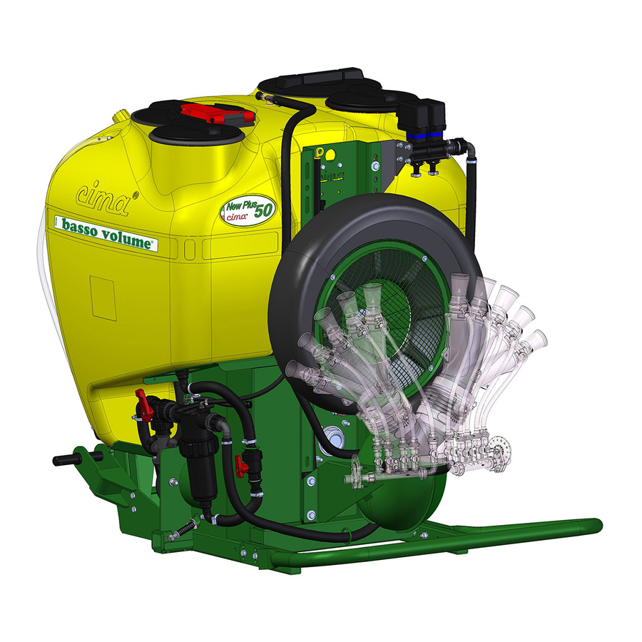
Page 40: Positioning Of Fan Casing
Plus 42 - 45 - 50 - 55 Plus 42 - 45 - 50 - 55 6.1 - POSITIONING OF FAN CASING 8.1.b Fan engagement to perform the treatment The fan’s air outlet must be positioned according to the distribution device to be mounted and the modality EXECUTION: in which it is to be utilised. -
Page 41: Accessories
Plus 42 - 45 - 50 - 55 Plus 42 - 45 - 50 - 55 FILLING ACCESSORIES FILLING MUST BE CARRIED OUT WITH THE MACHINE ON A FLAT SURFACE. ON THE SITE BEFORE 7.1 - FILLER PIPE THE OPERATION, THE DOSES OR THE MIXTURES TO BE POURED INTO THE TANK MUST BE The pipe is provided with a coupling elbow fitting and with a bottom-drawing valve. -
Page 42: Swivelling Device
Plus 42 - 45 - 50 - 55 Plus 42 - 45 - 50 - 55 3. Insert the wheels’ axle shafts into the ma- 7.4 - E.P.A. Kit - DELIVERY PROPORTIONAL ADVANCEMENT WHEEL WITH FRAME chine’s axle. AXLE SHAFT (for the version where foreseen) 4.
Need help?
Do you have a question about the PLUS and is the answer not in the manual?
Questions and answers