Table of Contents
Advertisement
Quick Links
Advertisement
Table of Contents

Related Manuals for Cima Plus 42


Summary of Contents for Cima Plus 42
- Page 1 OPERATION AND MAINTENANCE INSTRUCTIONS atomizzatori e impolveratori...
- Page 2 ! Our first goal, is to get our Customers happy for having met us! The “Spare parts catalogue” of this sprayer/sprayhead is available in the ‘“restricted area” on website www.cima.it. In order to accede, use: User name: sprayer Password: 844719KE...
- Page 3 LOW- VOLUME SPRAYING ATOMISER CARRIED Plus 42-45 Plus 50-55-55S-55E Serial Number: ........... OPERATING AND MAINTENANCE INSTRUCTIONS S.p.A. 27040 Montù Beccaria - Loc. Molino Quaroni - (PV) - ITALIA Tel. +39.0385.246636 r.a. - Fax +39.0385.246637 http://www.cimaitalia.com...
- Page 5 BASE from I to VI November 2000 from 1 to 53 November 2000 ADDITIONAL RECORDS AND VARIANTS REVISION DESCRIPTION First Edition, June 2000 Second Edition, November 2000 Plus 42 - 45 - 50 - 55 - 55S - 55E 11-2000...
- Page 6 COUPLING MODALITIES ....................23 CONNECTION TO THE TRACTOR .................. 23 TRANSMISSION SHAFT ASSEMBLING ................24 INSTALLATION OF REMOTE CONTROLS ..............24 5.3.1 Manual 2-tap distributor - P10 ....................24 Plus 42 - 45 - 50 - 55 - 55S - 55E 11-2000...
- Page 7 CLEANING OF FILTER CARTRIDGE ................42 13.3 PURGING OF RESIDUES FROM FILTER ................ 42 13.4 CLEANING OF THE FAN ....................42 13.5 FAN BELT TENSIONER ...................... 43 Plus 42 - 45 - 50 - 55 - 55S - 55E 11-2000...
- Page 8 INTEGRATIVE DIAGRAMS ....................50 16.1 HYDRO-PNEUMATIC DIAGRAM ..................50 16.2 ELECTRICAL CONNECTIONS ................... 51 AERIAL NOISE ........................52 WARRANTY ......................... 52 ATTACHMENT : COMPLIANCE DECLARATION ............53 Plus 42 - 45 - 50 - 55 - 55S - 55E 11-2000...
- Page 9 The following “symbols “ are utilised within the text in order to highlight and visually identify the Plus 42 - 45 - 50 - 55 - 55S - 55E 11-2000...
- Page 10 Should the machine be sold, the owner must inform the new purchaser that he should notify C.I.M.A S.p.A. of his address in order to receive possible future integrating issues and/or updates. GLOSSARY Plus 42 - 45 - 50 - 55 - 55S - 55E 11-2000...
- Page 11 3 - 95005 - DANGER, PARTS IN MOTION. BEFORE REMOVING PROTECTION GUARDS, STOP THE TRACTOR, REMOVE THE KEY FROM THE TRACTOR’S CONTROL PANEL AND ENSURE THAT ALL MOVING PARTS HAVE STOPPED Plus 42 - 45 - 50 - 55 - 55S - 55E 11-2000...
- Page 12 19 - 95058 - INDICATION ON THE OPERATION OF THE 3-WAY TAP (P5) - Positioned on the left-hand side of the tank, above the pump.. Positioning of the safety, utilisation and maintenance decals * Safety decals Plus 42 - 45 - 50 - 55 - 55S - 55E 11-2000...
- Page 13 * Operation and maintenance decals 00128 OPTONAL 00184 00129 00011 00130 Plus 42 - 45 - 50 - 55 - 55S - 55E 11-2000...
-
Page 14: General Information
3,30 atm MISCELAZIONE POLVERI MELANGE DE LA POUDRE MANUTENZIONE FILTRO COMPLAINTE DU FILTRE POWDER M IXING MEZCLA DE LOS POLVOS FILTER MAINTENANCE MANTENIM. DEL FILTRO 95058 95060 95058 Plus 42 - 45 - 50 - 55 - 55S - 55E 11-2000... -
Page 15: Safety Notices
— keep people and animals away from the machine before starting it up; — don’t wear articles of clothing that might get caught in moving parts; — keep to a low speed while negotiating humps or crossing ditches. Plus 42 - 45 - 50 - 55 - 55S - 55E 11-2000... -
Page 16: Safety Systems
TO MODIFY THE STRUCTURE OR THE SPECIFIC OPERATION OF THE SPRAY ATOMISER ITSELF. ANY INTERVENTION NOT SPECIFICALLY AUTHORISED BY C.I.M.A. S.p.A. IMMEDIATELY VOIDS ANY KIND OF WARRANTY AND CLEARS C.I.M.A. S.p.A. OF ANY CONSEQUENT AND/OR IMPLIED RESPONSIBILITY. Plus 42 - 45 - 50 - 55 - 55S - 55E 11-2000... - Page 17 3.5.3 - Disposal of empty containers and agro-chemicals residues Agro-chemicals are classified as “special” waste and their disposal must take place separately from “urban” wastes. Plus 42 - 45 - 50 - 55 - 55S - 55E 11-2000...
- Page 18 - when difficulty in breathing is experienced for the anti-dust filters of class P1 and In any case it is necessary to make use of all personal means of protection as suggested by the manufacturers. Plus 42 - 45 - 50 - 55 - 55S - 55E 11-2000...
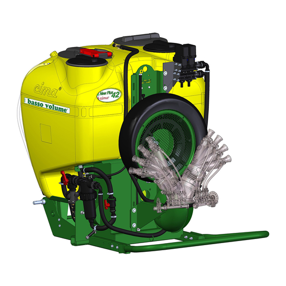
- Page 19 The pictures indicate the position of the main components of the spray atomiser. MAIN FILLER (BP) TANK DISTRIBUTION DEVICE (HEAD) CENTRIFUGAL ROTATING DISC REGULATOR 00129 JOINING HEAD FRAME ELBOW PROTECTION RING DELIVERY FILTER 00132 PUMP Plus 42 - 45 - 50 - 55 - 55S - 55E 11-2000...
- Page 20 (PTO) 4.1 - FRAME Frames of series Plus 42 and 45 can be coupled to category “1” hydraulic hoists. The plugs diameter is 22 mm. The diameter of the third-point plug is 19 mm. Frames of series Plus 50, 55, 55S and 55E can be coupled to category “2” hydraulic hoists.
- Page 21 The centrifugal close-propellers fan is built out of steel plate; the air intake on the housing is protected by an apposite grill. COLLAR SWINGING HOUSING PROTECTION GRILL SHAKER 00015 AIR INTAKE Plus 42 - 45 - 50 - 55 - 55S - 55E 11-2000...
- Page 22 P - E = elements of the circuit T = piping E11* TANK MIXER HYDRAULIC SHAKER TO THE DISTRIBUTION HEAD DELIVERY LOADING SUCTION FILLER PIPING (ACCESSORY) 00134 Hydraulic connections diagram Plus 42 - 45 - 50 - 55 - 55S - 55E 11-2000...
- Page 23 In order to carry out the complete discharge of any liquid remaining in the pump and pipes, set the tap to position “b”. 00019 Plus 42 - 45 - 50 - 55 - 55S - 55E 11-2000...
- Page 24 T2 TREATMENTS MUST BE CARRIED OUT ONLY WITH THE TAP IN THIS POSI- TION. 00136 Plus 42 - 45 - 50 - 55 - 55S - 55E 11-2000...
- Page 25 1 -1,5 atm, so as to allow for a better hydraulic 50 Pl shaking of the mixture. 00186 Plus 42 - 45 - 50 - 55 - 55S - 55E 11-2000...
- Page 26 This malfunction is signalled by the relevant gauge. This machine device only filters the feed flow to the heads, considerably reducing the chances of cartridge clogging. 00024 Plus 42 - 45 - 50 - 55 - 55S - 55E 11-2000...
- Page 27 They are open when the levers are set in the vertical position. They are closed when the levers are horizon- tal. 00077 00025 Plus 42 - 45 - 50 - 55 - 55S - 55E 11-2000...
- Page 28 It is necessary to carefully check the efficiency of the sealers and clam- ps, the tightening of the ring nuts and fittings and the good working condi- tion of the piping. 00026 Plus 42 - 45 - 50 - 55 - 55S - 55E 11-2000...
-
Page 29: Technical Data
4.4 - TECHNICAL DATA 4.4.1- Spray atomiser dimensions and weights (With protection ring - without distribution device - without accessories) 4.4.2 - Technical specifications for fans and pumps Centrifugal Fans Plus 42 - 45 - 50 - 55 - 55S - 55E 11-2000... - Page 30 For a good result of the treatments this condition MUST ALWAYS BE OBSERVED during the machine’s operation. Utilisation is permitted with speed rates ranging between 500 and 620 revs/min. Plus 42 - 45 - 50 - 55 - 55S - 55E 11-2000...
-
Page 31: Hitching To The Tractor
10. Block the coupling by tightening the chains of the hoister arms. When the operation is completed the 2 drive outlets (PTO) must be positioned on the same axis, both in vertical and horizontal direction. Plus 42 - 45 - 50 - 55 - 55S - 55E 11-2000... - Page 32 5.3.1 - Manual distributor with 2 taps - P10 1 – Mount the securing bracket on the tractor within the driver’s reach. 2 – Insert the distributor’s bayonet support in the securing bracket. Plus 42 - 45 - 50 - 55 - 55S - 55E 11-2000...
- Page 33 SECURING - Stop the tractor and remove the key BRACKET from the control panel. - Position tap P5 on “d”.. 00086 Plus 42 - 45 - 50 - 55 - 55S - 55E 11-2000...
-
Page 34: Distribution Devices
° e ° c i l 2 . I 2 . I 2 . I e f f Plus 42 - 45 - 50 - 55 - 55S - 55E 11-2000... - Page 35 WITHOUT ELBOW In the user and maintenance booklet of every distribution device the type of elbow necessary for the connection is specified together with the assembling instruc- tions. Plus 42 - 45 - 50 - 55 - 55S - 55E 11-2000...
- Page 36 AVOID OPERATING AND STANDING BENEATH THE MACHINE OR WITHIN THE AREA THAT MI- GHT BE INVOLVED IN ITS 00090 SUDDEN LOWERING. Plus 42 - 45 - 50 - 55 - 55S - 55E 11-2000...
- Page 37 It is an accessory utilised to modify the direction of the pulverising. It can be deployed only with some types of distribution devices. All indications and instructions are provided in the use and maintenance booklet of the distribution devices with which it can be used. Plus 42 - 45 - 50 - 55 - 55S - 55E 11-2000...
- Page 38 5. Reposition the mobile protection cover and fasten the locking screw properly. 6. Start the tractor, lift the spray atomiser to position the universal joint shaft and carry out the filling operation.. Plus 42 - 45 - 50 - 55 - 55S - 55E 11-2000...
- Page 39 5a1. Pour the dose of the medicinal in powder form into the cup-like filter through the main filler (BP) 5a2. Close the tank’s main filler (BP) 5a3. Open the filter’s knob tap (P8) 5a4. Set the lever of tap (P5) to the “b” position Plus 42 - 45 - 50 - 55 - 55S - 55E 11-2000...
- Page 40 - P6: is open (work position); NOTE: at first filling of the spray atomiser CHECK that the pressure regulator is in the OPEN position; - P7 and P3: are closed (lever on “c”); - P8: knob tap of the filter is closed. Plus 42 - 45 - 50 - 55 - 55S - 55E 11-2000...
- Page 41 14. Make sure that the fan is stopped. Hook the fan to the servo amplifier as indicated at point 8.1.b. 15. Start the tractor, always observing the safety norms. Plus 42 - 45 - 50 - 55 - 55S - 55E 11-2000...
- Page 42 16. Lift the machine. Activate the drive outlet (P.d.P.) and keeping it at 500 revs/min, perform a further shaking cycle. CARRY OUT THE TREATMENT. 00093 00094 00104 00033 00105 00140 00105 00107 Plus 42 - 45 - 50 - 55 - 55S - 55E 11-2000...
- Page 43 1. Unscrew the drain plug only when the tap’s lever is in the “a” position. (Drain closed). 2. Turn the lever to position “b”. (Drain open).. 00033 00133 Plus 42 - 45 - 50 - 55 - 55S - 55E 11-2000...
- Page 44 - the EFFICIENCY of the Distribution device (HEAD); - that the PULVERISING POINTS (DIFFUSERS) ARE CLEAN; - that the CARTRIDGE AND THE DELIVERY FILTER (P8) ARE CLEAN; Plus 42 - 45 - 50 - 55 - 55S - 55E 11-2000...
- Page 45 CARRYING OUT OF THEIR PREVENTION AND PROTECTION FUNCTIONS. • BEFORE STARTING THE TRACTOR, KEEP AWAY PERSONS OR ANIMALS AND NEVER LEAVE IT UNATTENDED DURING THE PREPARATION OPERATION. Plus 42 - 45 - 50 - 55 - 55S - 55E 11-2000...
- Page 46 Carry out the cleaning of the hydraulic circuit by washing the inner side of the tank with a clean water jet, then spraying it on the crop on which the treatment has just been completed: if necessary repeat this operation. Plus 42 - 45 - 50 - 55 - 55S - 55E 11-2000...
- Page 47 The use of detergent products for the cleaning operations is allowed only in the observance of the regulations in force. For these, the operator must gather the relevant information from the specifically appointed bodies ruling on this subject. Plus 42 - 45 - 50 - 55 - 55S - 55E 11-2000...
- Page 48 4. Position the spray atomiser on the transporting vehicle in perfectly stable conditions. 5. During transportation the machine must be immobilised and fastened to the carrier by way of suitable strapping. Plus 42 - 45 - 50 - 55 - 55S - 55E 11-2000...
-
Page 49: Maintenance Operations
• In case of intensive machine usage, reduce lubrication times accordingly. BELT-TENSIONER SUPPORT PUMP BEARINGS 00129 00128 FAN SHAFT BELT-TENSIONER SUPPORT FREE WHEEL 00130 Plus 42 - 45 - 50 - 55 - 55S - 55E 11-2000... - Page 50 COLLAR 6. Reassemble the casing paying particular 00097 attention to the perfect coupling with the rear cover. Plus 42 - 45 - 50 - 55 - 55S - 55E 11-2000...
- Page 51 Check length “L” of the spring (refer to Picture): it should be in tension between 4 and 5 cm. L = 4 ÷ 5 cm 00129 00099 Plus 42 - 45 - 50 - 55 - 55S - 55E 11-2000...
- Page 52 13. Reassemble the mobile protection lid of the disengaging device, by securing it with the relevant screw. 14. Reinstate the hydraulic and pneumatic connections. 00141 Plus 42 - 45 - 50 - 55 - 55S - 55E 11-2000...
- Page 53 : e r : r e : r e UMAPT12 Plus 42 - 45 - 50 - 55 - 55S - 55E 11-2000...
-
Page 54: Fault Finding
REMEDY: Refer to the C.I.M.A. service point. D. FAULT: Vibration of fan unit 1. CAUSE: Fan dirty. REMEDY: Clean. (It is advisable to refer to the C.I.M.A. service point). Plus 42 - 45 - 50 - 55 - 55S - 55E 11-2000... - Page 55 THE CAUSES AND REMEDIES FOR THE FAULTS CONCERNING THE DELIVERY OF THE PULVERISING BY ONE OR MORE DIFFUSERS ARE INDICATED IN THE USER AND MAINTENANCE MANUAL OF EVERY DISTRIBUTION DEVICE. Plus 42 - 45 - 50 - 55 - 55S - 55E 11-2000...
- Page 56 7. Re-assemble the steel-plate protection guards. STEEL-PLATE BELT-TENSIONER GUARD 00038 00100 GUARD SECURING SCREW PUMP TRAPEZOID BELT 00038 00014 00091 Carefully tighten the screws that were undone during the belt replacement. Plus 42 - 45 - 50 - 55 - 55S - 55E 11-2000...
- Page 57 2. Replace the faulty fuse and screw back the cover. · Fuse: 1.25 A, delayed. ALL OTHER INTERVENTIONS MUST BE CARRIED OUT BY A C.I.M.A. SERVICE POINT. ELECTRICAL CONTROL PANEL FUSE 00101 FUSE-HOLDER COVER Plus 42 - 45 - 50 - 55 - 55S - 55E 11-2000...
- Page 58 FILLER FILTER PIPING CONNECTION E11* E10* Cable W2 Cable W1 MAINS CONNECTOR ELECTRICAL ELECTRICAL DISTRIBUTOR CONTROL PANEL * For the versions in which it is envisaged 00143 Plus 42 - 45 - 50 - 55 - 55S - 55E 11-2000...
- Page 59 16.2 - ELECTRICAL COLLECTIONS 00001GB Plus 42 - 45 - 50 - 55 - 55S - 55E 11-2000...
-
Page 60: Rumore Aereo
Plus 42 - 45 - 50 - 55 - 55S - 55E 11-2000... - Page 61 19ATTACHMENT: DECLARATION OF COMPLIANCE19 Plus 42 - 45 - 50 - 55 - 55S - 55E 11-2000...
- Page 64 S.p.A. 27040 Montù Beccaria - Loc. Molino Quaroni - (PV) - ITALIA Tel. +39.0385.246636 r.a. - Fax +39.0385.246637 http://www.cimaitalia.com...
Need help?
Do you have a question about the Plus 42 and is the answer not in the manual?
Questions and answers