Cima PLUS Operation And Maintenance Instructions
Hide thumbs
Also See for PLUS:
- Operation and maintenance instructions (92 pages) ,
- Maintenance instruction (42 pages)
Table of Contents
Advertisement
Quick Links
Advertisement
Table of Contents

Subscribe to Our Youtube Channel
Related Manuals for Cima PLUS


Summary of Contents for Cima PLUS
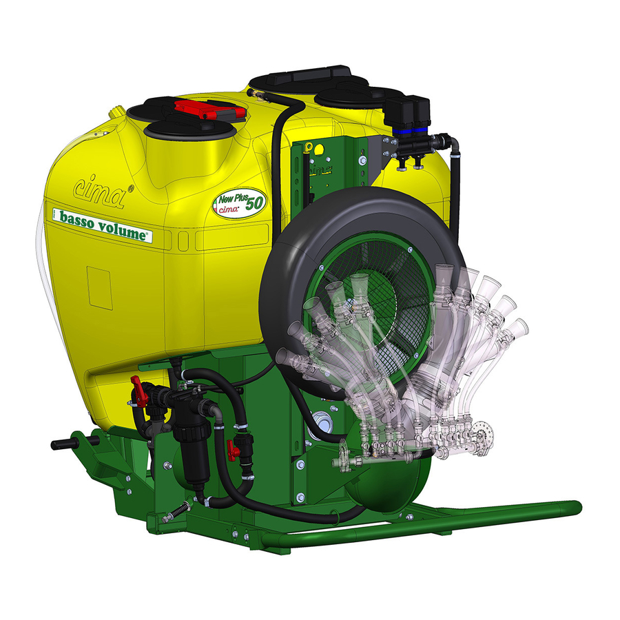
- Page 1 OPERATION AND MAINTENANCE INSTRUCTIONS atomizzatori e impolveratori...
- Page 2 ! Our first goal, is to get our Customers happy for having met us! The “Spare parts catalogue” of this sprayer/sprayhead is available in the ‘“restricted area” on website www.cima.it. In order to accede, use: User name: sprayer Password: 844719KE...
- Page 3 LOW-VOLUME SPRAYERS MOUNTED MODELS Plus 42-45 Plus 50-55-55S-55E Model: ........... Serial Number: ........... OPERATION AND MAINTENANCE INSTRUCTIONS S.p.A. 27040 Montù Beccaria - Loc. Molino Quaroni - (PV) - ITALIA Tel. +39.0385.246636 r.a. - Fax +39.0385.246637 http://www.cimaitalia.com...
- Page 5 1 to 55 January 2002 ADDITIONAL RECORDS AND VARIANTS REVISION DESCRIPTION First Edition, June 2000 Second Edition, November 2000 Revision, December 2001 Third edition, January 2002 Plus 42 - 45 - 50 - 55 - 55S - 55E 01-2002...
-
Page 6: Table Of Contents
HITCHING TO THE TRACTOR ..................23 MOUNTING OF THE TRANSMISSION SHAFT ..............24 INSTALLATION OF REMOTE CONTROLS ..............24 5.3.1 Manual 2-tap distributor - P10 ....................24 Plus 42 - 45 - 50 - 55 - 55S - 55E 01-2002... - Page 7 FAN SHAFT SUPPORT OIL LEVEL CHECK ..............42 13.3 FAN SHAFT SUPPORT OIL REPLACEMENT ..............42 13.4 CLEANING OF FILTER’S CARTRIDGE ................43 13.5 PURGING OF RESIDUES FROM FILTER ................ 43 Plus 42 - 45 - 50 - 55 - 55S - 55E 01-2002...
- Page 8 INTEGRATIVE DIAGRAMS ....................51 16.1 HYDRO-PNEUMATIC DIAGRAM ..................51 16.2 WIRING DIAGRAM ......................52 NOISE LEVEL ........................53 WARRANTY ......................... 53 ATTACHMENT : DECLARATION OF COMPLIANCE ............ 54 Plus 42 - 45 - 50 - 55 - 55S - 55E 01-2002...
-
Page 9: Foreword
All operations suggested by the manual will have to be followed with the utmost care and only after having understood the negative consequences of improper usage. Plus 42 - 45 - 50 - 55 - 55S - 55E 01-2002... -
Page 10: Updates
Should the machine be sold, the owner must inform the new purchaser that he should notify C.I.M.A S.p.A. of his address in order to receive possible future integrating issues and/or updates. Plus 42 - 45 - 50 - 55 - 55S - 55E 01-2002... -
Page 11: Glossary
2 - 95004 - DANGER OF CONTAMINATION BY CONTACT OR POISONOUS PRODUCTS INHALA- TION - Positioned above the tank, in the forward part, next to the filler spout. Plus 42 - 45 - 50 - 55 - 55S - 55E 01-2002... - Page 12 - Positioned on the tank, on the side of the electrical distributor. 18 - 95058 - INDICATION ON THE OPERATION OF THE 3-WAY TAP (P5) - Positioned on the left-hand side of the tank, above the pump.. Plus 42 - 45 - 50 - 55 - 55S - 55E 01-2002...
- Page 13 Positioning of the safety, use and maintenance decals 00128 OPTONAL 00184 00298 00011 00130 Plus 42 - 45 - 50 - 55 - 55S - 55E 01-2002...
- Page 14 MISCELAZIONE POLVERI MELANGE DE LA POUDRE MANUTENZIONE FILTRO COMPLAINTE DU FILTRE POWDER M IXING MEZCLA DE LOS POLVOS FILTER MAINTENANCE MANTENIM. DEL FILTRO 95058 95060 95069 95058 Plus 42 - 45 - 50 - 55 - 55S - 55E 01-2002...
-
Page 15: General Information
— check that the cardan shaft is blocked by the appropriate anti-rotation chains; — keep people and animals away from the machine before starting it up; Plus 42 - 45 - 50 - 55 - 55S - 55E 01-2002... -
Page 16: Safety Systems
ING INTERVENTION HAS TO BE CARRIED OUT EITHER AT THE DISTRIBUTORS’ OR AT THE C.I.M.A. S.p.A. AUTHORIZED WORKSHOPS, OTHERWISE ANY KIND OF WARRANTY IMMEDIATELY CEASES AND C.I.M.A. S.p.A. IS CLEARED OF ANY CONSEQUENT AND/OR IMPLIED RESPONSIBILITY. Plus 42 - 45 - 50 - 55 - 55S - 55E 01-2002... -
Page 17: Handling Of Agro-Chemicals
3.5.3 - Disposal of empty containers and agro-chemicals residues Agro-chemicals are classified as “special” waste and their disposal must take place separately from “urban” wastes. Plus 42 - 45 - 50 - 55 - 55S - 55E 01-2002... -
Page 18: Personal Means Of Protection
- when difficulty in breathing is experienced for the anti-dust filters of class P1 and In any case it is necessary to make use of all personal means of protection as suggested by the manufacturers. Plus 42 - 45 - 50 - 55 - 55S - 55E 01-2002... -
Page 19: Machine Structural Analysis
MAIN FILLER (BP) DISTRIBUTION DEVICE (HEAD) ELECTRICAL DISTRIBUTOR ROTATING DISC REGULATOR TANK 00296 JOINING HEAD FRAME ELBOW PROTECTION RING LEVER TAP FOR DUST PRODUCTS MIXING DELIVERY 00299 FILTER PUMP Plus 42 - 45 - 50 - 55 - 55S - 55E 01-2002... -
Page 20: Frame
ALL frames allow for the double positioning of plugs Frames of series Plus 50, 55, 55S and 55E can be coupled to category “2” three-point linkage. The plugs diameter is 28.5 mm. The diameter of the third-point plug is 25 mm. -
Page 21: Fan Servo Amplifier
The closed blades’ impeller is sheet steel realized and dynamically balanced; the air intake opening on the casing is protected by a grating, especially foreseen for this purpose. COLLAR SWINGING HOUSING PROTECTION GRILL SHAKER 00015 AIR INTAKE Plus 42 - 45 - 50 - 55 - 55S - 55E 01-2002... -
Page 22: Hydraulic Circuit Components
® Remote Control Spin Press. Pump TANK DUST PRODUCTS MIXER HYDRAULIC TO THE AGITATION DISTRIBUTION HEAD DELIVERY FILTER LOADING SUCTION FILLER PIPE (ACCESSORY) 00243 Hydraulic connections diagram Plus 42 - 45 - 50 - 55 - 55S - 55E 01-2002... - Page 23 In order to carry out the complete discharge of any liquid remaining in the pump and pipes, set the tap to position “b”. 00019 Plus 42 - 45 - 50 - 55 - 55S - 55E 01-2002...
- Page 24 T2 TREATMENTS MUST BE CARRIED OUT ONLY WITH THE TAP IN THIS POSI- TION. 00300 Plus 42 - 45 - 50 - 55 - 55S - 55E 01-2002...
- Page 25 1 -1,5 atm, so as to allow for a better hydraulic agitation of the mixture. 50 Pl 00186 Plus 42 - 45 - 50 - 55 - 55S - 55E 01-2002...
- Page 26 A soiled cartridge lowers of the operating pressu- This malfunction is signalled by the relevant gauge. 00302 This device only filters the flow to the heads, considerably reducing the chances of cartridge clogging. Plus 42 - 45 - 50 - 55 - 55S - 55E 01-2002...
- Page 27 They are open when the levers are set in the vertical position. They are closed when the levers are horizon- tal. Plus 42 - 45 - 50 - 55 - 55S - 55E 01-2002...
- Page 28 It is necessary to carefully check the efficiency of the sealers and clamps, the tightening of the ring nuts and fittings and the good working condi- tion of the piping. 00026 Plus 42 - 45 - 50 - 55 - 55S - 55E 01-2002...
-
Page 29: Technical Data
Fan diameter (mm) Fan speed (revs/min.) 4000 4500 4000 3500 3700 3900 Air flow rate (m 4000 5400 7550 12500 14000 15500 Air speed (m/s) Power absorbed (kW) Plus 42 - 45 - 50 - 55 - 55S - 55E 01-2002... - Page 30 MUST ALWAYS BE OBSERVED during the machine’s operation. Utilisation is permitted with speed rates ranging between 500 and 620 RPM Plus 42 - 45 - 50 - 55 - 55S - 55E 01-2002...
-
Page 31: Coupling Modalities
10. Block the coupling by tightening the chains of the hoister arms. When the operation is completed the 2 drive outlets (PTO) must be positioned on the same axis, both in vertical and horizontal direction. Plus 42 - 45 - 50 - 55 - 55S - 55E 01-2002... -
Page 32: Mounting Of The Transmission Shaft
5.3.1 - Manual 2-tap distributor - P10 1 – Mount the securing bracket on the tractor within the driver’s reach. 2 – Insert the distributor’s bayonet support in the securing bracket. Plus 42 - 45 - 50 - 55 - 55S - 55E 01-2002... -
Page 33: Electrical Control Panel - E10
MOUNTING - Stop the tractor and remove the key BRACKET from the control panel. - Position tap P5 on “d”. 00086 Plus 42 - 45 - 50 - 55 - 55S - 55E 01-2002... -
Page 34: Distribution Devices
France type, 2 lower hands and 2 upper cannons head TCF.2M2C.45P02 TCF.2M2C.50P02 TCF.2M2C.55P.02 France type, 2 lower hand and 4 upper cannons head TCF.2M4C.45P02 TCF.2M4C.50P02 TCF.2M4C.55P02 Hydraulic movement head TCI.2M4C.45P11 TCI.2M4C.50P11 TCI.2M4C.55P11 Coffee head T.CA.45P.01 T.CA.50P.01 Plus 42 - 45 - 50 - 55 - 55S - 55E 01-2002... -
Page 35: Positioning Of Fan Casing
WITHOUT ELBOW In the use and maintenance book-let of every distribution device the type of elbow necessary for the connection is specified together with the assembling instruc- tions. Plus 42 - 45 - 50 - 55 - 55S - 55E 01-2002... -
Page 36: Accessories
AVOID OPERATING AND STANDING BENEATH THE MACHINE OR WITHIN THE AREA THAT 00090 MIGHT BE INVOLVED IN ITS SUDDEN LOWERING. Plus 42 - 45 - 50 - 55 - 55S - 55E 01-2002... -
Page 37: Manual Turn Device
It is an accessory utilised to modify the direction of the pulverising. It can be used only with some types of distribution devices. All indications and instructions are provided in the use and maintenance booklet of the distribution devices with which it can be used. Plus 42 - 45 - 50 - 55 - 55S - 55E 01-2002... -
Page 38: Filling
5. Reposition the mobile protection cover and fasten the locking screw properly. 6. Start the tractor, lift the sprayer to position the universal joint shaft and carry out the filling operation. Plus 42 - 45 - 50 - 55 - 55S - 55E 01-2002... -
Page 39: Fan Engagement To Perform The Treatment
6a1. Pour the dose of powder into the cup-like filter through the main filler (BP). 6a2. Close the tank’s main filler (BP). 6a3. Open the tap (P8) (lever on “a”). Plus 42 - 45 - 50 - 55 - 55S - 55E 01-2002... -
Page 40: Filling With The Specific Pipe
- P6, pressure regulator: is completely open for the unit’s first use, or on the already selected position for the outstanding treatment or for the previous one. Plus 42 - 45 - 50 - 55 - 55S - 55E 01-2002... - Page 41 15. Make sure that the fan is stopped. Hook the fan to the servo amplifier as indicated at point 8.1.b. 16. Start the tractor, always observing the safety norms. Plus 42 - 45 - 50 - 55 - 55S - 55E 01-2002...
- Page 42 18. Close the cock (P7) (lever on “c”) 19. CARRY OUT THE TREATMENT. 00093 00094 00104 00033 00105 00140 00245 00105 Plus 42 - 45 - 50 - 55 - 55S - 55E 01-2002...
-
Page 43: Agitation
2. Turn the lever to position “b”. (Drain open). 3. After having carried out the draining, turn the lever to the position “a” (Draining closed) and screw again the draining plug. DRAINING PLUG 00133 Plus 42 - 45 - 50 - 55 - 55S - 55E 01-2002... -
Page 44: Operating Procedures
- the EFFICIENCY of the Distribution device (HEAD); - that the SPRAYING POINTS (DIFFUSERS) ARE CLEAN; - that the CARTRIDGE AND THE DELIVERY FILTER (P12) ARE CLEAN; - FAN SHAFT SUPPORT OIL LEVEL. Plus 42 - 45 - 50 - 55 - 55S - 55E 01-2002... - Page 45 CARRYING OUT OF THEIR PREVENTION AND PROTECTION FUNCTIONS. • BEFORE STARTING THE TRACTOR, KEEP AWAY PERSONS OR ANIMALS AND NEVER LEAVE IT UNATTENDED DURING THE PREPARATION OPERATION. Plus 42 - 45 - 50 - 55 - 55S - 55E 01-2002...
-
Page 46: The Treatment
Check the efficiency of the distribution device (head) and the cleaning of the pulverising points (diffusers), possibly replacing them if found to be damaged. Plus 42 - 45 - 50 - 55 - 55S - 55E 01-2002... -
Page 47: End Of Seasonal Cycle
The use of detergent products for the cleaning operations is allowed only in the observance of the regulations in force. For these, the operator must gather the relevant information from the specifically appointed bodies ruling on this subject. Plus 42 - 45 - 50 - 55 - 55S - 55E 01-2002... -
Page 48: Lifting And Transport
4. Position the sprayer on the transporting vehicle in perfectly stable conditions. 5. During transport the machine must be immobilised and fastened to the carrier by way of suitable strapping. Plus 42 - 45 - 50 - 55 - 55S - 55E 01-2002... -
Page 49: Maintenance Operations
• Carefully clean the greasing nipples and the oil filler in order to avoid that, during lubrication, dirt might be introduced. FAN SHAFT SUPPORT CONTROLLARE CHECK BELT-TENSIONER CONTRÔLER SUPPORT CONTROLAR PUMP BEARINGS 00128 00298 FREE WHEEL 00130 Plus 42 - 45 - 50 - 55 - 55S - 55E 01-2002... -
Page 50: Fan Shaft Support Oil Level Check
- about 0,10 kg for the PLUS 42 and 45 models - about 0,18 kg for the PLUS 50 and 55 models. 5. Position again the plug with the dipstick and close the oil filling pipe. Plus 42 - 45 - 50 - 55 - 55S - 55E 01-2002... -
Page 51: Cleaning Of Filter's Cartridge
Dirt accumulation or incrustations can unbalance the fan, inducing vibrations that could cause breakage LEGEND 1. UNION ELBOW FASTENING COLLAR 2. FAN CASING 3. IMPELLER 4. SCREW NUT 00251 5. FAN CASING FASTENING COLLAR Plus 42 - 45 - 50 - 55 - 55S - 55E 01-2002... -
Page 52: Fan Belt Tensioner
Check length “L” of the spring (refer to picture): it should be in tension between 4 and 5 cm. L = 4 ÷ 5 cm 00099 00298 Plus 42 - 45 - 50 - 55 - 55S - 55E 01-2002... -
Page 53: Tank Removal Or Replacement
13. Reassemble the mobile protection lid of the disengaging device, by securing it with the relevant screw. 14. Reinstate the hydraulic and pneumatic connections. 00141 Plus 42 - 45 - 50 - 55 - 55S - 55E 01-2002... -
Page 54: Table Of Maintenance Operations
COMPLETELY DRAIN AND WASH Sprayer: EXTERIOR WASHING Sprayer: STORAGE Wheel hubs' fastening screws: CHECK THE TIGHTENING Wheels' fastening screw nuts: CHECK THE TIGHTENING Tyre pressure: CHECK UMAPT12GB Plus 42 - 45 - 50 - 55 - 55S - 55E 01-2002... -
Page 55: Faults Finding
REMEDY: Refer to the C.I.M.A. service point. D. FAULT: Vibration of fan unit 1. CAUSE: Fan dirty. REMEDY: Clean. (It is advisable to refer to the C.I.M.A. service point). Plus 42 - 45 - 50 - 55 - 55S - 55E 01-2002... - Page 56 THE CAUSES AND REMEDIES FOR THE FAULTS CONCERNING THE DELIVERY OF THE SPRAYING BY ONE OR MORE DIFFUSERS ARE INDICATED IN THE USE AND MAINTENANCE MANUAL OF EACH SPRAYHEAD. Plus 42 - 45 - 50 - 55 - 55S - 55E 01-2002...
-
Page 57: Repairs Allowed
7. Re-assemble the steel-plate protection guards. STEEL-PLATE BELT-TENSIONER GUARD 00038 00100 GUARD SECURING SCREW PUMP TRAPEZOID BELT 00038 00014 00091 Carefully tighten the screws that were undone during the belt replacement. Plus 42 - 45 - 50 - 55 - 55S - 55E 01-2002... -
Page 58: Replacement Of Electrical Panel's Fuses
4. Mount the new pressure gauge, by carrying out in reverse order the steps mentioned for its removal. ANY OTHER INTERVENTION HAS TO BE CARRIED OUT AT A C.I.M.A. CUSTOMERS’ SERVICING CENTER. 50 Pl 2000 00309 Plus 42 - 45 - 50 - 55 - 55S - 55E 01-2002... -
Page 59: Integrative Diagrams
PUMP FILLER PIPING CONNECTION E11* E10* Cable W2 Cable W1 MAIN CONNECTOR ELECTRICAL ELECTRICAL DISTRIBUTOR CONTROL PANEL * For the versions in which it is envisaged 00246 Plus 42 - 45 - 50 - 55 - 55S - 55E 01-2002... -
Page 60: Wiring Diagram
16.2 - WIRING DIAGRAM 00001GB Plus 42 - 45 - 50 - 55 - 55S - 55E 01-2002... -
Page 61: Noise Level
Plus 42 - 45 - 50 - 55 - 55S - 55E 01-2002... -
Page 62: Attachment: Declaration Of Compliance
19 ATTACHMENT: DECLARATION OF COMPLIANCE 19 Plus 42 - 45 - 50 - 55 - 55S - 55E 01-2002... - Page 64 S.p.A. 27040 Montù Beccaria - Loc. Molino Quaroni - (PV) - ITALIA Tel. +39.0385.246636 r.a. - Fax +39.0385.246637 http://www.cimaitalia.com...
Need help?
Do you have a question about the PLUS and is the answer not in the manual?
Questions and answers
Pump has no pressure
The Cima PLUS pump could have no pressure due to the following causes:
1. Insufficient water in the tank to trigger the pump.
2. Air being sucked into the filler piping.
3. Hydraulic circuit not sealing properly.
4. Pump’s belt slipping.
5. Broken pump belt.
This answer is automatically generated