Table of Contents
Advertisement
Advertisement
Table of Contents

Related Manuals for Dover Marathon RAMJET Signature Series


Summary of Contents for Dover Marathon RAMJET Signature Series
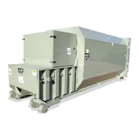
- Page 1 OPERATION, MAINTENANCE, AND INSTALLATION MANUAL RJ-88SC RJ-100SC RJ-250SC RJ-250SC Ultra Includes HT (Hydraulic Tailgate) Units and SL (Streamline, Liquid Removal) Units SELF-CONTAINED COMPACTOR CONTAINER Marathon Equipment Co. OMI Manual No. 0018 Rev. 1/11...
-
Page 2: Table Of Contents
Table of Contents OPERATION Introduction ......................3 Specifications ......................4 Pre-Operating Instructions ..................5 Control Panel ......................6 Operating Instructions - Standard Models ..............7 Operating Instructions - Models with Photoelectric Cycle Control ........8 Optional Controls ....................... 9 Decals ........................10 Decal Placement ...................... -
Page 3: Introduction
1 OPERATION INTRODUCTION THANK YOU FOR PURCHASING A MARATHON SELF-CONTAINED COMPACTOR/CONTAINER. This compactor is designed to give you reliable and superior performance for many years to come. The purpose of this manual is to provide the owner and operator with the necessary information to properly and safely install, operate, and maintain your self contained compactor. -
Page 4: Specifications
1 OPERATION SPECIFICATIONS “B” Fire Hose Port “A” One per Side SIDE VIEW “D” Container “C” Compactor “E” 250SC 88SC 100SC 250SC 250SC HT ULTRA "A", Clear Top Opening 30 1/2 x 48 35 x 60 41 1/2 x 60 41 1/2 x 60 41 1/2 x 60 (Length x Width) (inches) "B", (inches) -
Page 5: Pre-Operating Instructions
1 OPERATION PRE-OPERATION INSTRUCTIONS FEDERAL REGULATION PROHIBITS THE USE OF THIS EQUIPMENT BY ANYONE UNDER 18 YEARS OF AGE. THE EMPLOYER SHOULD ALLOW ONLY AUTHORIZED TRAINED PERSONNEL OPERATE THIS COMPACTOR. This compactor is equipped with a key operated locking system. The key (s) should be in the possession of authorized personnel. -
Page 6: Control Panel
1 OPERATION CONTROL PANEL MANUAL - OFF - AUTOMATIC SWITCH* KEYED START SWITCH OPERATOR REVERSE PUSHBUTTON STATION FOR 88SC, 100SC, 250SC, & 250 ULTRA EMERGENCY STOP PUSHBUTTON *Optional equipment - not included on standard models CONTROL DESCRIPTION 1. MANUAL - OFF - AUTOMATIC SWITCH - ( Optional Equipment - not included on standard models ) This switch controls the compactor operation mode, manual or automatic... -
Page 7: Operating Instructions - Standard Models
1 OPERATION OPERATING INSTRUCTIONS - STANDARD MODELS 1. First, place the material to be discarded into the compactor. DANGER Note: If you are loading the compactor through a door or gate, close it before starting the compactor. Refer to DO NOT “Optional Loading Configurations”... -
Page 8: Operating Instructions - Models With Photoelectric Cycle Control
1 OPERATION OPERATING INSTRUCTIONS - Models with Photoelectric Cycle Control OPERATING INSTRUCTIONS (AUTOMATIC MODE) DANGER 1. Place the material to be discarded into the compactor. DO NOT NOTE: If you are loading the compactor through a door or ENTER gate, close it before starting the compactor. 2. -
Page 9: Optional Controls
1 OPERATION OPTIONAL CONTROLS 1. SUSTAINED MANUAL PRESSURE CONTROL BUTTON (Hold-To-Run, Release-To-Stop) This option requires the compactor operator to remain at the push button station while the compactor is in use. Actuation requires depressing the "Hold-To-Run" and "Start" buttons. After the unit has started, the "Start" button is released. If the "Hold-To-Run" button is released, the unit will stop instantly. -
Page 10: Decals
1 OPERATION DECALS WARNING DECAL REQUIREMENTS When your compactor leaves the factory, several WARNING DECALS are installed for your protection. These labels are subject to wear and abuse due to the nature of operation. The FOLLOWING DECALS MUST BE MAINTAINED. Additional decals may be purchased through your distributor or from Marathon Equipment Company by either calling the parts department at 1-800-633-8974 or going to www.parts1stop.com to place an order online. -
Page 11: Decal Placement
1 OPERATION DECALS PLACEMENT Match reference numbers to chart on previous page. See next page for decal images. * INSTALLED ON BOTH SIDES OF COMPACTOR IN SAME LOCATION **ALSO INSTALLED ON REMOTE POWER PACK... -
Page 12: Decal Images
1 OPERATION DECAL IMAGES 06-0038 06-0249 06-0057 06-0002 06-0072 06-0121 06-0124 06-3123 06-0067 06-0364 06-0057 06-0094 06-1836 06-0093 06-0104 06-3231 06-0105 06-0052... -
Page 13: Decal Placement For Optional Loading Configuration
1 OPERATION DECALS - Optional Loading Configurations Match reference numbers to “Decals” on page 10 when ordering replacement decals. THRU-THE WALL SECURITY CHUTE DOGHOUSE 16** 2 & 17 DOCK ACCESS GATE & HOPPER * Located on each inside wall ** Located on each outside wall... -
Page 14: Additional Decals For Hydraulic Tailgate (Ht) Units
1 OPERATION Decals - Additional For Hydraulic Tailgate (HT) Units In addition to the decals and their placement specified on the previous pages, the self contained units with the hydraulic tailgate option require the following decals located as shown below. HYDRAULIC COUPLING 19, BOTH SIDES SIDE VIEW... - Page 15 This Page Intentionally Left Blank...
-
Page 16: Maintenance
2 MAINTENANCE LOCK-OUT & TAG-OUT INSTRUCTIONS FOREWORD: Before entering any part of the compactor, be sure that all sources of energy have been shut off, all potential hazards have been eliminated, and the compactor is locked-out and tagged-out in accordance with OSHA and ANSI requirements. If the ram is pressing against a load, move the ram rearward before shutting the compactor down. -
Page 17: Periodic Maintenance
2 MAINTENANCE PERIODIC MAINTENANCE WARNING: RAM SPEED ACCELERATES AS RAM RETRACTS. NEVER ENTER ANY PART OF THE SELF-CONTAINED COMPACTOR/CONTAINER UNTIL THE UNIT HAS BEEN LOCKED-OUT AND TAGGED-OUT. MONTHLY Check external hoses for chafing, rubbing, or other deterioration and damage. Check for any obvious unsafe conditions in the compactor area. Check oil level in hydraulic reservoir. -
Page 18: Procedures - (Hydraulic System Pressure Check)
2 MAINTENANCE PROCEDURES PRESSURE SETTING INSTRUCTIONS When the hydraulic cylinders used in the RamJet Self-Contained compactor are fully extended or retracted, they bypass internally. This makes it impossible for the hydraulic system to reach relief pressure. Follow the recommendations below for proper pressure setting. 1. -
Page 19: Principles Of Operation
2 MAINTENANCE PRINCIPLES OF OPERATION STANDARD SYSTEM OPERATING CHARACTERISTICS, 5 hp & 10 hp The system uses special cylinders to move the ram and two timers to control the operation of the ram. When the hydraulic cylinders used in the self-contained compactors are fully extended or retracted, they bypass internally. -
Page 20: Tailgate Seal Replacement
2 MAINTENANCE TAILGATE SEAL REPLACEMENT When the door/tailgate seal becomes damaged or worn, replace the seal. WARNING: For units with hydraulic tailgates, before performing any inspection or maintenance on the seal, support the raised tailgate with a crane, forklift, or other positive maintenance prop.. -
Page 21: Fuse & Circuit Breaker
2 MAINTENANCE CHARTS FUSES AND CIRCUIT BREAKERS FULL LOAD DUAL CIRCUIT SERVICE MOTOR AMPS ELEMENT FUSE BREAKER DISCONNECT SIZE MAX.SIZE MAX. SIZE AMPS 5 HP, 1 PH 22.0 20.8 5 HP, 3 PH 13.8 13.4 10 HP, 1 PH 43.0 39.0 10 HP, 3 PH 27.5... -
Page 22: Wire Sizes/Heater Element
2 MAINTENANCE CHARTS WIRE SIZE THW Copper 75°C (165°F) MOTOR SIZE VOLTAGE UP TO 100’ UP TO 200’ UP TO 300’ 5 HP, 1 PH 5 HP, 3 PH 10 HP, 1 PH 10 HP, 3 PH MOTOR STARTERS AND HEATER ELEMENTS MOTOR SIZE VOLTAGE STARTER SIZE... -
Page 23: Typical Panel Box
2 MAINTENANCE TYPICAL PANEL BOX CONFIGURATION The diagram at right represents a typical panel box configuration for the self-contained compactors. The panel box on your compactor may differ depending on the model and/or optional equipment/ controls. Refer to t h e c h a r t b e l o w i d e nt i f y... -
Page 24: Plc - Layout And Description
2 MAINTENANCE PLC MAINTENANCE - LAYOUT & DESCRIPTION Reference Description Retractable mounting feet Screw terminal block for the power supply LCD, 4 lines, 18 characters Screw terminal block for inputs Screw terminal block for discrete input Connector for backup memory or PC connection cable Shift key Selection and validation key (Menu / Ok) Relay output screw terminal block... -
Page 25: Plc - Maintenance And Programming
2 MAINTENANCE PLC MAINTENANCE - continued MULTICYCLE COUNTER SELECTION STEPS DIRECTIONS Press the Menu Button Press Arrow Down Button to select PARAMETER (flashing) Press Menu/Ok Button Press Arrow Up Button until CC2 (flashing) Press Arrow Left Button until P=0001 is (flashing) Press Arrow Down or Arrow Down to select cycle count* Press Menu/Ok Button Press Menu/Ok Button with YES to Confirm Changes... -
Page 26: Power Unit - Standard 5 Hp
2 MAINTENANCE POWER UNIT - STANDARD 5 HP (MECO) Match the reference numbers to the chart on the next page. -
Page 27: Power Unit - Standard 5 Hp - (Parts List)
2 MAINTENANCE POWER UNIT - STARDARD 5 HP - Parts Lists (MECO) Match reference numbers with the chart on the previous page to identify components. For replacement part ordering, call our parts department at 1-800-633-8974 or log on to www.parts1stop.com to quickly place your order online. Part # Ref. -
Page 28: Power Unit - Standard 10 Hp - (Meco)
2 MAINTENANCE POWER UNIT - DRY 10 HP (MECO) -
Page 29: Power Unit - Standard 10 Hp - (Parts List) (Meco)
2 MAINTENANCE POWER UNIT - DRY 10 HP - Parts List (MECO) MATCH REFERENCE NUMBERS WITH THE DRAWING ON THE PREVIOUS PAGE. TO ORDER REPLACEMENT PARTS CALL OUR PARTS DEPARTMENT AT 1-800-633-8974 OR ON THE INTERNET AT www.parts1stop.com. Part # Ref. -
Page 30: Power Unit - Standard 10 Hp - (Non Meco)
2 MAINTENANCE POWER UNIT - DRY 10 HP (NON MECO) EXPLODED VIEW ISOMETRIC VIEW TOP VIEW SIDE VIEW... -
Page 31: Power Unit - Standard 10 Hp - (Parts List) (Non Meco)
2 MAINTENANCE POWER UNIT - DRY 10 HP - Parts List (NON MECO) MATCH REFERENCE NUMBERS WITH THE DRAWING ON THE PREVIOUS PAGE. TO ORDER REPLACEMENT PARTS CALL OUR PARTS DEPARTMENT AT 1-800-633-8974 OR ON THE INTERNET AT www.parts1stop.com. Part # Ref. -
Page 32: Power Unit - Submerged 10 Hp
2 MAINTENANCE POWER UNIT - SUBMERGED 10 HP (NON MECO) EXPLODED VIEW ISOMETRIC VIEW TOP VIEW SIDE VIEW SIDE VIEW - with LID... -
Page 33: Power Unit - Submerged 10 Hp - (Parts List)
2 MAINTENANCE POWER UNIT - SUBMERGED 10 HP - Parts List (NON MECO) MATCH REFERENCE NUMBERS WITH THE DRAWING ON THE PREVIOUS PAGE. TO ORDER REPLACEMENT PARTS CALL OUR PARTS DEPARTMENT AT 1-800-633-8974 OR ON THE INTERNET AT www.parts1stop.com. Part # Ref. -
Page 34: Hydraulic Schematic - Typical
2 MAINTENANCE HYDRAULIC SCHEMATIC - TYPICAL (cycon) 1. Cylinder 2. Quick Disconnect (Female) 3. Quick Disconnect (Male) 4. Valve, 4-Way 5. Relief Valve 6. Check Valve 7. Pump 8. Suction Filter 9. Hub Coupling (Not on Closed-Coupled Units) 10. Motor SINGLE CYCLINDER UNIT SHOWN. -
Page 35: Troubleshooting
2 MAINTENANCE TROUBLESHOOTING CHART PROBLEM CAUSE SOLUTION UNIT WILL NOT START ( 1) No electrical power to unit ( 1A) Turn on main disconnect ( 1B) Replace fuses or reset breakers ( 2) No electrical power to control ( 2A) Check primary and secondary circuit sides of transformer ( 2B) Check for correct voltage. - Page 36 2 MAINTENANCE TROUBLESHOOTING CHART PROBLEM CAUSE SOLUTION PUMP MAKES NOISE-SOUNDS LIKE GRAVEL ( 1 ) Partly clogged intake strainer or ( 1A) Pump must receive intake fluid restricted intake pipe freely or cavitation results. Drain system, clean intake pipe and clean or replace strainer ( 2) Defective bearing ( 2A) Replace pump...
-
Page 37: Installation
3 INSTALLATION CONCRETE PAD REQUIREMENTS CAUTION! REVIEW THIS MANUAL BEFORE MAKING THE INSTALLATION. STUDY THE JOBSITE AND INSTALLATION REQUIREMENTS CAREFULLY TO BE CERTAIN ALL NECESSARY SAFEGUARDS AND OR SAFETY DEVICES ARE PROVIDED TO PROTECT ALL PERSONNEL AND EQUIPMENT DURING THE INSTALLATION AND AS A COMPLETED SYSTEM. -
Page 38: Steel Installation Procedures
3 INSTALLATION STEEL INSTALLATION PROCEDURES DOCK INSTALLATION If the appropriate accessories are ordered from Marathon Equipment Co., the compactor/ container will be furnished with either a four-sided hopper or a three-sided hopper with a hinged gate. THESE ACCESSORIES SHOULD NOT BE ALTERED AS THEY ARE MANUFACTURED IN ACCORDANCE WITH THOSE STANDARDS WHICH PREVAIL AT THE TIME OF MANUFACTURE. -
Page 39: Electrical & Hydraulic Installation
3 INSTALLATION ELECTRICAL & HYDRAULIC INSTALLATION DANGER The motor control panel contains high voltage components. Only authorized service personnel should be allowed inside. See Lock-Out & Tag-Out in- VOLTS structions in the maintenance section. A lockable fused disconnect switch (customer furnished) must be installed and be within sight of the compactor motor control panel location, not to exceed 50'0"... -
Page 40: Through-The-Wall Power Unit Installation
3 INSTALLATION ELECTRICAL & HYDRAULIC INSTALLATION PUSHBUTTON CONTROL PANEL If a remote operator station is furnished, it will be factory wired using Sealtite. If it is necessary to disconnect it from the wires (to install the operator station inside a building), exercise care that these wires are reconnected as originally furnished. - Page 41 3 INSTALLATION THROUGH-THE-WALL POWER UNIT INSTALLATION If the remote power unit is to be mounted through-the-wall, the following list of material and diagram is the suggested method. List of Material Item # Quantity Description Hydraulic Hose, Hi-Pressure (sized to power unit*), 36” long Pipe, Schedule 80 (sized to power unit*), 36”...
-
Page 42: Hauler Information
4 HAULER INFORMATION HAULER INSTRUCTIONS - GENERAL Before hauling to the landfill: 1. Disconnect all hoses and electrical connections (if applicable) between the power unit and the compactor. Make sure they are placed in an area where they will not get damaged. 2. -
Page 43: Hauler Instructions - Door/Latch Operation
4 HAULER INFORMATION DOOR/LATCH OPERATION CONTAINER LATCH ASSEMBLY DOOR ACTUATED BY RATCHET LATCH SIDE VIEW AUTO RELATCH OF CONTAINER SAFETY CHAIN - ALWAYS FASTEN RATCHET FOR OPENING AND CLOSING CHAIN IN KEYHOLE THE LATCH ASSEMBLY WHEN DOOR IS CLOSED. WHEN THE DOOR IS OPEN, SECURE THE CHAIN IN THE KEYHOLE ON... -
Page 44: Hauler Instructions - Hydraulic Tailgate Operation (For Optional Ht Units)
4 HAULER INFORMATION HYDRAULIC TAILGATE OPERATION (FOR OPTIONAL HT UNITS) The truck hoist must have a hydraulic selector valve with 1500 psi, min. to operate the hydraulic tailgate. The hydraulic tailgate is supplied with one 1/2” NPTF male quick disconnect mounted on the drivers side of the unit. -
Page 45: Hauler Instructions - Tailgate Maintenance Bar (For Optional Ht Units)
4 HAULER INFORMATION HYDRAULIC TAILGATE OPERATION (FOR OPTIONAL HT UNITS) WARNING: NEVER PLACE ANY PART OF YOUR BODY BETWEEN THE TAILGATE AND CONTINER. INSTRUCTIONS FOR USING MAINTENANCE BAR. 1. Lower tailgate approximately 24” between container bottom and compactor tailgate. Remove locking pin from maintenance bar and slide bar toward compactor. 3. -
Page 46: Hauler Instructions - Liquid Removal (For Optional Sl Units)
4 HAULER INFORMATION LIQUID REMOVAL - (FOR OPTIONAL SL UNITS The RamJet Self-Contained Streamline compactor/containers are designed with an internal drain system for liquid removal, ported to each corner of the machine. The unit comes standard with one ball valve. This valve can be moved to any of the four drain outlets on the machine. - Page 47 This Page Intentionally Left Blank...
Need help?
Do you have a question about the Marathon RAMJET Signature Series and is the answer not in the manual?
Questions and answers