Table of Contents
Advertisement
Quick Links
Advertisement
Table of Contents

Related Manuals for Carel HEOS BOX R744


Summary of Contents for Carel HEOS BOX R744
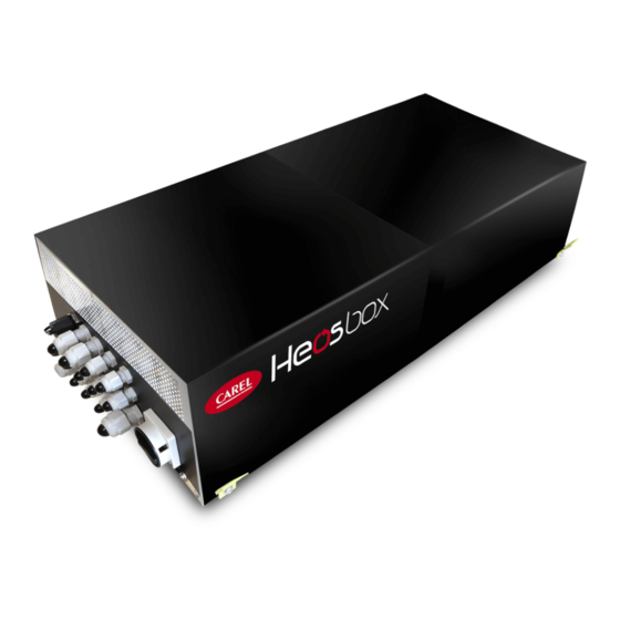
- Page 1 HEOS BOX R744 Assembly instructions, including user and maintenance information CE version User manual NO POWER & SIGNAL CABLES TOGETHER READ CAREFULLY IN THE TEXT! I n t e g r a t e d C o n t r o l S o l u t i o n s & E n e r g y S a v i n g s...
-
Page 3: Table Of Contents
2. GENERAL FEATURES AND SCOPE OF THE SUPPLY 2.1 Description of HEOS BOX ................7 2.2 Single and multi-evaporator configurations with ......HEOS BOX R744 ....................7 2.3 Heosbox models and valve selection ...........7 2.4 Accessories available ..................8 2.5 Connection diagrams: local and supervisor connection ..8 2.6 Technical data ....................10... -
Page 5: Warnings
Every product supplied by CAREL Industries, in relation to its advanced level of technology, requires setup/configuration/programming to be able to operate in the best possible way for the specific application. Failure to complete such operations, which are required/indicated in the user manual, may cause the final product to malfunction;... - Page 6 HEOS BOX complies with the following directives in force: liabilities deriving from the installation or use of the product, even if CAREL Industries or its subsidiaries/affiliates are warned of the possibility of such damage.
-
Page 7: General Features And Scope Of The Supply
E2VCABS9U0 Unipolar stator cable, 9m long Tab. 2.b The Heosbox units must be combined with a Carel unipolar electronic expansion valve, which is not supplied with the unit. Appropriate sizing of the electronic valve, where possible using Carel’s selection tools, allows Heosbox to be used for medium or low temperature applications. -
Page 8: Accessories Available
• to the showcase display, with local wireless connectivity, Bluetooth or NFC, via the “Applica” app. For further details see the controller manual +0300145EN; • to the supervisory system, Carel or third party, either via serial or Ethernet connection. The possible configurations for connection to the supervisory system are shown below. - Page 9 Wireless network functional diagram for single evaporator configuration ® ® ® Fig. 2.d By default, the Heos controller inside the unit is equipped with one Ethernet port only, and therefore an external switch is needed for connection to the supervisory system. Ethernet switch Ethernet network (Modbus) ®...
-
Page 10: Technical Data
Technical data Technical data for CE versions HB200C0300CE0 HB200C0400CE0 HB200C0600CE0 HB200C1000CE0 Power supply 220-240 220-240 220-240 380-400 [Ph] [Hz] 50-60 50-60 50-60 50-60 Max current draw without auxiliaries (1) 11.00 15.80 10.4 Max condensing unit current draw (2) 39.8 42.4 47.2 33.8 Nominal medium temperature cooling capacity (3) -
Page 11: Electrical Specifications Of The Auxiliary Loads
Electrical specifications Notice: auxiliary loads 1. The total current that can be supplied by the electronic controller, in the maximum load condition, must not exceed 25 A. The calculation Notice: wiring inputs provided with cable glands; electrical of the current supplied by the electronic control does not include the connections and cable gland tightening to be performed by the installer. -
Page 12: 2.10 Refrigerant Circuit
2.10 Refrigerant circuit Water outlet connection Water inlet connection Condenser Water Inlet Condenser Water Outlet Temper. Probe Temper. Probe Safety pressure Discharge switch Pressure Transducer Condenser Outlet Temperature Probe Condendenser Liquid Line Discharge Line Check valve Discharge Pressure Port Liquid receiver Safety valve Liquid Discharge Temperature... -
Page 13: 2.11 Electrical Panel
2.11 Electrical panel 55 44 Fig. 2.j Key: Ref. Description Ref. Description Cable gland for temperature sensors Inverter Cable gland for supervisor serial communication (or optional WiFi gateway Heos electronic controller kit serial communication) Inverter protection fuses Cable gland for Fieldbus communication Heos electronic controller fuses Cable gland for Ethernet Anti-sweat heater kit terminals... -
Page 14: Requirements For Positioning The Unit And ....................................... Multi-Evaporator Layout
A showcase B showcase C The section of the refrigerant circuit connecting the Heos Box R744 and the unit must be designed to avoid oil retention, which could prevent oil from returning to the compressor and consequent reliability and operating problems. - Page 15 Heos Box higher than the evaporator showcase A showcase B showcase C o s b 5 m max height difference Suction line P-trap H e o s b o Fig. 2.p Fig. 2.o Heos Box lower than the evaporator • Ensure that the pressure inside the “dead-end branches” does not Reverse-trap exceed the maximum allowed value •...
- Page 16 Minimum cooling capacity in kW to ensure the oil is carried through an evaporator with 1 circuit T_evap T_cond Piping nominal outside diameter (OD), mm °C °C 0.179 0.457 0.798 1.393 2.198 3.117 4.235 6.933 0.169 0.432 0.754 1.318 2.079 2.949 4.006 6.558...
- Page 17 Minimum cooling capacity in kW to ensure the oil is carried through an evaporator with 2 circuits T_evap T_cond Piping nominal outside diameter (OD), mm °C °C 0.633 1.615 2.820 4.927 7.772 11.023 14.976 24.518 0.598 1.527 2.667 4.659 7.349 10.422 14.161 23.182...
- Page 18 MT application (medium temperature): Minimum cooling capacity in kW to ensure the oil is carried in the suction piping T_evap T_cond Piping nominal outside diameter (OD), mm °C °C 0.494 1.262 2.204 3.850 6.074 8.614 11.704 19.160 0.468 1.193 2.085 3.642 5.745 8.147...
-
Page 19: Handling
HANDLING Opening the packaging • outdoors, in a place where it is exposed to the weather; • in positions where the relative humidity is > 80% and condensing; • Check that the unit is intact upon delivery and notify the carrier •... - Page 20 wall Caution: the Heos Box supporting structure is designed to support the module’s own weight only with the covers closed and screwed on. Make sure the Box is placed on a flat surface or equivalent support system before opening the covers. Furthermore, adequate clearances must be ensured in all directions, except for the support base needed for correct operation of the unit;...
-
Page 21: Installation
Caution: The PS and TS values for the water circuit connected to the • install automatic air vent valves (not supplied by CAREL) in the piping, at HEOS BOX refer to the lowest PS or TS of all the components in the circuit. -
Page 22: Feedwater Specifications
The installer is responsible for the correct construction and balancing of rator Model orator (suction outlet the water circuit. Carel Industries S.p.A. declines all liability for water loop (liquid line) (to be piped) line) installations that do not comply with the aforementioned instructions and HB200C0300CE0 diam. -
Page 23: Electrical Connections
Electrical connections Caution: the refrigerant connections must always be completed by qualified personnel who have the qualifications and authorisations Caution: the electrical panel closing panel is connected to the rest required by local regulations, using appropriate personal protective of the structure by an earth wire (yellow/green). If this wire is removed equipment (PPE), who are aware of the necessary precautions and who are during installation, before closing the panel make sure to connect it again, able to correctly and safely complete all required operations. -
Page 24: Kit Installation
Notice: the length of the earth wire for the electronic controller main power supply and digital output connections should be minimised, CAREL Industries S.p.A. may in this case, based on specific agreements, act using the earthing points provided inside the electrical panel (positions 41 as a consultant for the design/installation/commissioning/use of the unit, and 42 in Figure 2.j) . -
Page 25: Oil Top-Up Requirements
10. Disconnect the pump and close the discharge pressure port (Fig. 2.i, 3) one pressure transducer installed inside the Heos Box 11. Carefully open the refrigerant inlet and outlet shut-off valves (Fig. 2.i, CAREL Industries S.p.A. recommends using the default superheat set 18 and 21) points configured in the system. -
Page 26: Refrigerant Discharging Procedure
Refrigerant discharging procedure 4.10 Commissioning checklist The following points should be considered general indications for correctly discharging refrigerant from the unit, and are not technical specifications. For details on the parameter settings and SW functions in In the event of welding or cutting operations on the refrigerant circuit (e.g. general, see the controller manual +0300145EN to replace a component), it is recommended to completely discharge all of the R744 refrigerant contained in the system. -
Page 27: Maintenance
Temporarily remove the protective panels on the refrigerant circuit compartment and the electrical panel, and make sure the following are absent: Notice: if replacing the Carel PSD inverter, when restarting the unit, make sure that the Heos controller writes the “PEC” safety parameters to the inverter. -
Page 28: Accessory Kit Installation
ACCESSORY KIT INSTALLATION Secondary multi-evaporator panel 11 12 13 14 15 16 17 Fig. 6.a Fig. 6.b Ref. Description Ref. Description Electrical panel main switch Cable gland for Fieldbus serial communication Optional WiFi gateway kit Cable gland for Ethernet RJ45 port Cable gland for digital output 3 Cable gland for valve stator power cable Cable gland for digital output 5... -
Page 29: Wifi Gateway Kit
The multi-evaporator electrical panel is designed to be placed above or, if necessary, underneath the showcase. Regarding the electrical connections, the same warnings apply as for the HEOS module. See the wiring diagram supplied with the panel as regards the electrical connections, the description of the cable glands/connectors and the functions these are intended for. - Page 30 Notes Heos BOX R704 +0300140EN - rel. 1.0 - 25.05.2022...
- Page 32 Caution: Do not remove this copy of the unit label from the manual. The customer is required to carefully keep all of the documentation supplied with the unit for any future maintenance or service. CAREL INDUSTRIES - Headquarters Via dell’Industria, 11 - 35020 Brugine - Padova (Italy) Tel.
Need help?
Do you have a question about the HEOS BOX R744 and is the answer not in the manual?
Questions and answers