
Related Manuals for PEERLESS PANA-85WM


Summary of Contents for PEERLESS PANA-85WM
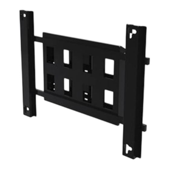
- Page 1 Installation and Assembly: Wall Mount for Panasonic TH-85PF12U and TH-85VX200U Model: PANA-85WM Landscape Portrait Maximum Load Capacity: 270 lb (122 kg) 1 of 8 ISSUED: 12-18-09 SHEET #: 125-9090-4 03-24-11...
- Page 2 IMPORTANT! Read instruction sheet before you start installation and assembly. WARNING • Do not begin to install your Peerless product until you have read and understood the instructions and warnings contained in this Installation Sheet. If you have any questions regarding any of the instructions or warnings, for US customers please call Peerless customer care at 1-800-865-2112, for all international customers, please contact your local distributor. • This product should only be installed by someone of good mechanical aptitude, has experience with basic building construction, and fully understands these instructions. • Make sure that the supporting surface will safely support the combined load of the equipment and all attached hardware and components. • Never exceed the Maximum Load Capacity. See page one. • If mounting to wood wall studs, make sure that mounting screws are anchored into the center of the studs. Use of an "edge to edge" stud finder is highly recommended. • Always use an assistant or mechanical lifting equipment to safely lift and position equipment. • Tighten screws firmly, but do not overtighten. Overtightening can damage the items, greatly reducing their holding power. • This product is intended for indoor use only. Use of this product outdoors could lead to product failure and personal injury. • This product was designed to be installed on the following wall construction only; WALL CONSTRUCTION HARDWARE REQUIRED • Wood Stud...
- Page 3 Parts List Description Qty. Part # A wall plate 201-1697 B tilt plate 201-1695 C support tube 201-1693 D adapter bracket 201-1692 E rectangle cap 590-1334 F M8 x 15 mm phillips screw 520-9257 G M5 x 8 mm phillips screw 570-0005 H 8 mm anchor 590-0320 #14 x 2.5 wood screw 5S1-015-CO3 J 5/16 split washer 540-9405 K 5/16 washer 540-9406 L lock bracket 201-1698...
- Page 4 Installation to Triple Wood Stud Wall WARNING • Installer must verify that the supporting surface will safely support the combined load of the equipment and all attached hardware and components. • Tighten wood screws so that wall plate is firmly attached, but do not overtighten. Overtightening can damage the screws, greatly reducing their holding power. • Never tighten in excess of 80 in. • lb (9 N.M.). • Make sure that mounting screws are anchored into the center of the stud. The use of an "edge to edge" stud finder is highly recommended. • Hardware provided is for attachment of mount through standard thickness drywall or plaster into wood studs. Install- ers are responsible to provide hardware for other types of mounting situations. Use a stud finder to locate the edges of the studs. Use of an edge-to-edge stud finder is highly recommended. Based on their edges, draw a vertical line down each stud’s center. Place wall plate (A) on wall as a template. Level plate, and mark the center of the nine mounting holes. Make sure that the mounting holes are on the stud centerlines. Drill nine 5/32" (4 mm) dia. holes 2.5" (64 mm) deep. Make sure that the wall plate is level, secure it using nine #14 x 2.5" wood screws (I) as shown. Skip to step 2. 4 of 8 ISSUED: 12-18-09 SHEET #: 125-9090-4 03-24-11...
- Page 5 Installation to Solid Concrete or Cinder Block WARNING • When installing Peerless wall mounts on cinder block, verify that you have a minimum of 1-3/8" (35 mm) of actual concrete thickness in the hole to be used for the concrete anchors. Do not drill into mortar joints! Be sure to mount in a solid part of the block, generally 1" (25 mm) minimum from the side of the block. Cinder block must meet ASTM C-90 specifications. It is suggested that a standard electric drill on slow setting is used to drill the hole instead of a hammer drill to avoid breaking out the back of the hole when entering a void or cavity. • Concrete must be 2000 psi density minimum. Lighter density concrete may not hold concrete anchor. • Make sure that the wall will safely support four times the combined load of the equipment and all attached hardware and components. Make sure that wall plate (A) is level, use it as a template to mark nine mounting holes. Drill nine 5/16" concrete surface (8 mm) dia. holes to a minimum depth of 2.5" (64 mm). Insert anchors (H) in holes flush with wall as shown in figure 1.1. Place wall plate over anchors and secure with nine #14 x 2.5" screws (I). Level, then tighten all fasteners as shown in fig. 1.2. Drill holes and insert anchors (H). WARNING • Tighten screws so that wall plate is firmly attached, but do not overtighten. Overtightening can damage Place plate (A) over anchors (H) and secure with screws (I).
- Page 6 Secure two support tubes (C) to tilt plate (B) using four M8 x 15 mm phillips screws (F), four 5/16 split washers (J), and four 5/16 washers (K). Secure four rectangle caps (E) to support tubes (C) as shown. Landscape Portrait Secure two adapter brackets (D) to support tubes (C) using eight M8 x 15 mm phillips screws (F), eight 5/16 split washers (J), and eight 5/16 washers (K) to create bracket assembly. NOTE: Be sure keyholes point down. Keyhole Keyhole Landscape Portrait 6 of 8 ISSUED: 12-18-09 SHEET #: 125-9090-4 03-24-11...
- Page 7 To make sure bracket assembly keyhole are properly aligned with standoffs, position bracket assembly onto display standoffs. Remove bracket assembly from back of display. Display Secure tilt plate (B) of bracket assembly to wall plate (A) at desired tilt angle using six M8 x 15 mm phillips screws (F), six 5/16 split washers (J), and six 5/16 washers (K).Secure one M8 x 15 mm phillips screws (F), 5/16 split washer (J), and 5/16 washer (K) into slot of tilt plate (B) as shown in Detail 1. 0° 5° 10° Slot Detail 1 F,J, and K Mounting Surface Not Shown for Clarity Landscape Portrait 7 of 8 ISSUED: 12-18-09 SHEET #: 125-9090-4 03-24-11...
- Page 8 Hook display standoffs into keyhole slots on adapter brackets (D) of bracket assembly. NOTE: Make sure that standoffs rest at the bottom of keyhole slots as shown in detail 2. Secure display standoffs in keyhole using two lock brackets (L) and M5 x 8 mm phillips screws (G) as shown in detail 3. Display Detail 3 Landscape Keyhole Mounting Surface Not Shown for Clarity Display Standoff Detail 2 Display Detail 3 Keyhole Portrait Display Standoff Mounting Surface Not Shown for Clarity Detail 2 8 of 8 ISSUED: 12-18-09 SHEET #: 125-9090-4 03-24-11...
Need help?
Do you have a question about the PANA-85WM and is the answer not in the manual?
Questions and answers