Advertisement
Quick Links
Installation & Assembly
IMPORTANT!
Read entire instruction sheet before you start assembly and installation.
Parts List
PART #
QTY.
A 200-1434
1
B 200-1877
1
C 520-1055
2
D 200-0288
1
E 520-1001
1
F 520-9263
12
G 590-1087
1
H 520-9250
4
I
200-1311
1
J 200-0342
1
K 520-9260
1
L 200-1338
1
M 590-0097
4
N 540-1008
4
O 5SI-015-C03
4
P 560-9646
1
Note: Some parts may appear slightly different than illustrated.
Note: Lay flat on sufrace for ease of assembly.
Place swivel lock bracket (I) on wall arm assembly (J)
as shown to the right.
Place rotation box (A) with threaded holes up over
wall arm assembly (J). Insert tilt pivot retainer
assembly (B) through rotation box (A) and wall arm
assembly (J).
Secure rotation box (A) to swivel lock bracket (I) using
four M5 x .8 x 10 mm phillips screws (H). Align holes
in tilt pivot retainer assembly (D) with holes in rotation
box (B) and secure with two 10-32 x 1/2" socket pin
screws (C) as shown.
A
THREADED
HOLES
B
Visit the Peerless Web Site at www.peerlessindustries.com
-
Solid•Point
Before you start make sure all parts
listed are included with your product.
DESCRIPTION
rotation box
tilt pivot retainer assembly
10-32 x 1/2" socket pin screw
pitch roll assembly
carriage bolt 3/8"-16 x 3"
M10 x 1.5 x 15 mm penta-pin screw
tilt adjustment knob
M5 x .8 x 10 mm phillips screw
swivel lock bracket
wall arm assembly
™
M10 x 2" penta-pin
driver
wall plate
concrete anchor
fender washer
wood screw
4 mm security allen wrench
I
J
™
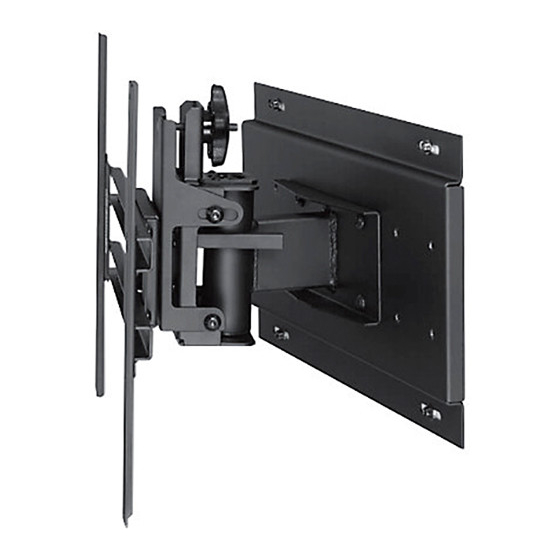
Wall Mount with Tilt and Swivel
A
C
D
E
K
H
F
I
A
B
C
1 of 6
For customer service call 1-800-729-0307 or 708-865-8870.
Model: PS 1
B
M
J
P
N
O
Hole in bottom of
rectangular tube
denotes bottom of
wall arm assembly.
J
H
I
J
ISSUED: 07-03-02 SHEET #: 200-9386-6 01-25-11
I
G
L
Advertisement

Related Manuals for PEERLESS Solid-Point PS 1


Summary of Contents for PEERLESS Solid-Point PS 1
- Page 1 (B) and secure with two 10-32 x 1/2" socket pin screws (C) as shown. THREADED HOLES 1 of 6 ISSUED: 07-03-02 SHEET #: 200-9386-6 01-25-11 Visit the Peerless Web Site at www.peerlessindustries.com For customer service call 1-800-729-0307 or 708-865-8870.
- Page 2 CENTER SPACER BOLT THREADED HOLE WASHER M5 SCREW RETAINING M5 SCREW SPACER SLOT DETAIL 4 DETAIL 4A 2 of 6 ISSUED: 07-03-02 SHEET #: 200-9386-6 01-25-11 Visit the Peerless Web Site at www.peerlessindustries.com For customer service call 1-800-729-0307 or 708-865-8870.
- Page 3 WARNING • When installing Peerless wall mounts on cinder block, verify that you have a minimum of 1 5/8" of actual concrete surface in the 1/4" diameter hole to be used for the concrete anchors. Do not drill into mortar joints! Be sure to mount in a solid part of the block, generally 1"...
- Page 4 Attach wall arm assembly (J) to wall plate (L) using four M10 penta-pin screws (F). 4 of 6 ISSUED: 07-03-02 SHEET #: 200-9386-6 01-25-11 Visit the Peerless Web Site at www.peerlessindustries.com For customer service call 1-800-729-0307 or 708-865-8870.
- Page 5 (G), then securely tighten all four M10 screws (F) using penta-pin driver (K). AS A FINAL PRECAUTION, CHECK ALL FASTENERS AND TIGHTEN SECURELY. 5 of 6 ISSUED: 07-03-02 SHEET #: 200-9386-6 01-25-11 Visit the Peerless Web Site at www.peerlessindustries.com For customer service call 1-800-729-0307 or 708-865-8870.
- Page 6 Visit the Peerless Web Site at www.peerlessindustries.com For customer service call 1-800-729-0307 or 708-865-8870. © 2004 Peerless Industries, Inc. All rights reserved. Peerless is a registered trademark of Peerless Industries, Inc. All other brand and product names are trademarks or registered trademarks of their respective owners.
Need help?
Do you have a question about the Solid-Point PS 1 and is the answer not in the manual?
Questions and answers