Table of Contents
Advertisement
Quick Links
Advertisement
Table of Contents

Summary of Contents for Samsung SSC-2000
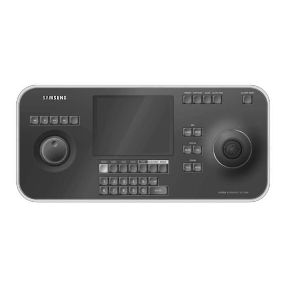
- Page 1 System Keyboard SSC-2000 User's Manual...
- Page 2 This symbol indicates high voltage is present inside. It is dangerous to make any kind of contact with any inside part of this product. This symbol alerts you that important litera- ture concerning operation and maintenance has been included with this product. To prevent damage which may result in fire or electric shock hazard, do not expose this appliance to rain or moisture.
- Page 3 Adjusting System Keyboard Angle ...gb-5 Fixing Power Cord ...gb-5 Connecting RS-485 Device ...gb-5 Connecting PC by RS-232 ...gb-7 Connecting Other System Keyboard ...gb-7 Basic System Diagram of SSC-2000 ...gb-7 Log-in ...gb-8 Camera control ...gb-8 DVR control ...gb-11 MUX control ...gb-11 <...
- Page 4 - PATTERN - SCAN - AUTO PAN The Pan/Tilt connected with Samsung Dome Camera or Receiver Unit is moved to UP/DOWN/LEFT/RIGHT. Press the button on the top of Joystick to control the Auto Focus. And use for the zoom control by turning to the clockwise or counterclockwise.
- Page 5 • Please refer to “RS-485 Communication Setup (GB-12)” of “Chapter 5. Menu Setup” for RS-485 communication setup. - Connect with SSC-2000 by using the RS-485 port on the back of Dome Camera • In case of connecting with Half Duplex - Connect the Txd (+) of Dome Camera RS-485 port with the Tx (+) of SSC-2000.
- Page 6 - Connect SSC-2000 through the RS-232C port in the back of SHR-4040. - You may use the RS-232 to 485 converter. - Connect with SSC-2000 by using the RS-485 port on the back of SHR-4080 • In case of connecting with Half Duplex - Connect the Tx (+) of SHR-4080 RS-485 port with the Tx (+) of SSC-2000.
- Page 7 M E N U M O N C A N M U X M O D E - Connect the Tx (+) of SSC-2000 port with the Tx (+) of another SSC-2000. - Connect the Tx (-) of SSC-2000 RS-485 port with the Tx (-) of another SSC-2000.
- Page 8 1. Turn on the power of all the components of the system. 2. When the power is applied by connecting the power adapter at the back of system keyboard, the following indication is displayed on the LCD screen. 3. Using the keypad of the touch screen or the number key of the keyboard, enter the registered Operator number (1~32) and press “Enter”.
- Page 9 This function is to view the camera movement for 30 seconds desig- nated by the user on the pattern mode of the camera menu. Press the pattern button on the keyboard, enter the pattern number(1~3) you want, and press “ENTER” to execute PATTERN movement. “PATTERN 1”...
- Page 10 English small letter input page will appear. Press “TEXT” if you want to enter large letters. Press “NUMBER” if you want to enter numbers. Press “SYMBOL” if you want to enter symbols. Press a word at a time until you complete the title you want. Maximum 14 characters can be entered.
- Page 11 MENU. Press the EXIT ICON to clear the camera menu. • When you control the menu of SAMSUNG DOME CAMERA, you can use the joystick as a direction or enter key by moving it or after pressing the AF button of it.
- Page 12 1. Press the “CH” ICON below on the MUX screen. 2. A channel selection screen will appear as shown below. 3. Select the channel you want. 4. Press the EXIT ICON on the lower right to finish selecting and return to the MUX control screen Press the setup icon on the lower left to control the menu of the selected MUX.
- Page 13 The address of the system keyboard can be set. Press “ADDRESS SET” and the keyboard address input window will appear as shown below. Enter the address by using the number keys and press the enter key. Press enter the “EXIT” ICON on lower left if you want to clear the window without entering the address.
- Page 14 The PARITY BIT of RS-232 communication can be set. Press “PARITY CHECK” and a pop-up window will appear as shown below. Select one among None / Odd / Even. The STOP BIT of RS-232 communication can be set. Press “STOP BIT” and a pop-up window will appear as shown below. Choose one between 1 / 2.
- Page 15 • DEFAULT OPERATOR LEVEL is OPERATOR level. Please refer to the chapter 6.”OPERATOR LEVEL” for the details. This function is to download the setup data of SAMSUNG DOME CAMERA. - If you want to download the data for the first time Download the setup data of the currently selected camera.
- Page 16 When you press “OK” on the UPLOAD check screen, UPLOAD progress screen will appear as shown below. ‘Complete’ message will appear when uploading is completed. - S/W Version : Present version. Setup impossible. - Factory Default Setup : Reset all the menu values to the initial default value.
- Page 17 ITEM DESCRIPTION INTERFACE (RS-485) CONNECTOR TYPE : 4P TERMINAL TYPE PORT : 1 PORT BAUD RATE : 4,800/9,600/19,200/38,400bps INTERFACE (RS-232C) CONNECTOR TYPE : D-SUB 9P PORT : 1 PORT BAUD RATE : 600/1,200/2,400/4,800/ 9,600/19,200/38,400/57,600bps LCD PANEL 5.7” GRAPHIC PANEL (320X240line) + TOUCH PANEL VIEWING ANGLE : LEFT(39º),RIGHT(32º), REAR(10º), FRONT(30º)


Need help?
Do you have a question about the SSC-2000 and is the answer not in the manual?
Questions and answers