Table of Contents
Advertisement
Quick Links
Advertisement
Table of Contents

Subscribe to Our Youtube Channel
Related Manuals for PAW HeatBloC K34R


Summary of Contents for PAW HeatBloC K34R
- Page 1 PAW GmbH & Co. KG Böcklerstr. 11, 31789 Hameln - Germany Phone: +49-5151-9856-0, Fax: +49-5151-9856-98 E-mail: info@paw.eu, Web: www.paw.eu Installation and Operation Instructions HeatBloC® K34R DN 25 / DN 32 DN 25 DN 32 2021/07 993x0663Mx-mub-en – V01...
- Page 2 Translation of the original instructions PAW GmbH & Co. KG We reserve the right to make technical changes without notice! Böcklerstraße 11 Printed in Germany – Copyright by PAW GmbH & Co. KG 31789 Hameln - Germany 993x0663Mx-mub-en – V01 2021/07...
-
Page 3: Table Of Contents
1 General Information Contents General Information ......................4 Scope of these instructions ..................4 Designated use ......................4 Safety instructions ......................5 Product description ......................6 Equipment ........................7 Function ........................8 3.2.1 Check valve and non-return valve ............... 10 3.2.2 Pump [specialist] .................... -
Page 4: General Information
Improper usage of the HeatBloC® excludes any liability claims. This product complies with the relevant directives and is therefore labelled with the CE mark. The Declaration of Conformity is available upon request, please contact the manufacturer. Only use PAW accessories with the HeatBloC®. 993x0663Mx-mub-en – V01 2021/07... -
Page 5: Safety Instructions
2 Safety instructions 2 Safety instructions The installation and commissioning as well as the connection of electrical components require technical knowledge commensurate with a recognised vocational qualification as a fitter for plumbing, heating and air conditioning technology, or a profession requiring a comparable level of knowledge [specialist]. -
Page 6: Product Description
The pump can thus be maintained easily without draining the heating circuit system. The HeatBloC® is designed such that it can be directly mounted onto a PAW distribution manifold or a mounting plate. -
Page 7: Equipment
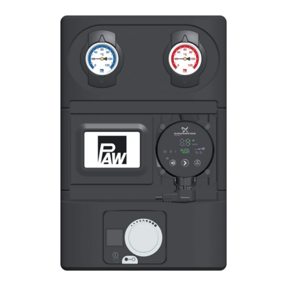
3 Product description 3.1 Equipment Flow to the consumer circuit Full metal thermometer with immersion sleeve, integrated in the ball valve (flow) Heating pump 3-way mixing valve with adjustable bypass 0-50 % Flow from the heat generator Return to the heat generator Non-return valve, can be opened Weather compensated controller PWR6 Check valve, can be opened... -
Page 8: Function
3 Product description Function K34R: 3-way mixing valve with bypass 0-50 % The flow temperature of the heating circuit is controlled by the integrated mixing valve. Hot water from the boiler and cold return water are mixed to obtain the desired flow temperature of the heating circuit. - Page 9 3 Product description Application range: Consumer circuits with weather compensated • low-temperature heating systems controlled by a mixing valve Consumer circuits with high flow rates, • e.g. radiant floor heating and radiant panel heating systems Return flow temperature maintenance • (then, bypass is closed) 2021/07 993x0663Mx-mub-en –...
-
Page 10: Check Valve And Non-Return Valve
3 Product description 3.2.1 Check valve and non-return valve The HeatBloC® is equipped with a check valve (D-1, opening pressure 200 mm wc) in the return pipe and with a non-return valve (C-3, opening pressure 50 mm wc) in the return of the mixing valve. -
Page 11: Pump [Specialist]
3 Product description 3.2.2 Pump [specialist] The pump can be completely isolated. It can be replaced and maintained without draining the heating circuit system. Isolation of the pump: 1. Disconnect the expansion tank from the installation. 2. Close the ball valves in the flow and the return (A-2, F-2). 3. - Page 12 3 Product description 1. During commissioning, determine the optimum bypass position for the operation of the installation. Find out and check the correct adjustment through a trial-and-error process. If the slot of the bypass screw is in a vertical position, the bypass is closed. If the HeatBloC®...
- Page 13 3 Product description Change of the flow line [specialist] Dismounting of the mixing valve 1. Take off the thermometer handles (A-2, F-2) and remove the insulating front shell. 2. Take the group of fittings out of the insulating back shell. 3.
- Page 14 Mixing valve with flow on the left 12. Turn the cover plate (4) in such a way that the marking "PAW" is at the bottom (in direction of the external threads) and that the scale is positioned as shown in the figure above.
-
Page 15: Weather Compensated Controller Pwr6
3 Product description Weather compensated controller PWR6 The weather compensated controller PWR6 is prepared for the direct mounting onto the 3-way bypass mixing valve of the HeatBloC® K34R. If the controller is connected to the power supply for the first time, an initial commissioning must be carried out. -
Page 16: Installation Of The Weather Compensated Controller Pwr6
3 Product description Installation of the weather for mixing valve with flow on the right: compensated controller PWR6 1. Turn the rotary knob of the mixing valve into position "5". Fig. 1 2. When the weather compensated controller is delivered, it is in centre position. By disengaging the gear (●push○), you can adjust the controller at the rotary knob. -
Page 17: Mounting And Installation [Specialist]
4 Mounting and installation [specialist] 4 Mounting and installation [specialist] The HeatBloC® K34R can be mounted on a PAW modular distribution manifold or on a wall bracket. The modular distribution manifold and the wall bracket are optional accessories and are thus not included in the scope of delivery. - Page 18 4 Mounting and installation [specialist] Option 2: on a mounting plate with Option 3: directly on a wall bracket. • • transition thread connections. consumer circuit return flow return flow return flow return flow heat generator Please observe the separate and respectively corresponding instructions regarding the installation of the distribution manifold, of the mounting plate and of the wall bracket.
- Page 19 HeatBloC®. 2. Unscrew the nuts on the lower connections of the HeatBloC® and take out the sealing rings. If a PAW modular distribution manifold or transition connection is used: 3. Put the two nuts over the flanges. flange (side view) 4.
-
Page 20: Accessories: Cutting-Ring Compression Fitting (Not Included In The Scope Of Delivery)
4 Mounting and installation [specialist] Accessories: Cutting-ring compression fitting (not included in the scope of delivery) The connection to the heating installation can be carried out fast, pressure-proof and without soldering if you use the optionally available compression fittings. 1. Push the union nut ② and the cutting ring ③ onto the copper pipe ①. -
Page 21: Scope Of Delivery [Specialist]
5 Scope of delivery [specialist] 5 Scope of delivery [specialist] NOTICE Complaints and requests/orders of spare parts will only be processed with information on the serial number! The serial number is placed on the return pipe of the heating circuit. Spare parts DN 25 2021/07 993x0663Mx-mub-en –... - Page 22 5 Scope of delivery [specialist] Pos. Description Item no. no pos. Sealing set for mixing valve 37013 Thermo ball valve DN 25, F1" x 1" int. thread, snap-in assembly N00244 Thermometer handle for thermo ball valve 1" x ¼" N00248 Dial thermometer, red scale, d = 50 mm, 0-120 °C N00242 Union nut G 1½''...
-
Page 23: Spare Parts Dn 32
5 Scope of delivery [specialist] Spare parts DN 32 2021/07 993x0663Mx-mub-en – V01... - Page 24 5 Scope of delivery [specialist] Pos. Description Item no. no pos. Sealing set for mixing valve 41013 Thermo ball valve DN 32, F1¼“ x 1¼“ int. thread, snap-in N00245 assembly Union nut G2'' 2156 Gasket 1¼“ for threaded connection G2" N00133 Pump see following table Dial thermometer, blue scale, d = 50 mm, 0-120 °C...
-
Page 25: Technical Data
6 Technical data 6 Technical data K34R DN 25 (1") DN 32 (1¼") Dimensions Centre distance (1) 125 mm 125 mm Width insulation (2) 250 mm 250 mm Height insulation (3) 383 mm 441 mm Installation length (4) 340 mm 400 mm Connections Outlet (A-1, F-1) -
Page 26: Pressure Drop And Pump Characteristic Curves Dn 25
6 Technical data K34R DN 25 (1") DN 32 (1¼") Hydraulics Max. pressure 6 bars 6 bars Max. temperature 110 °C 110 °C -value [m 10.1 Pressure drop and pump characteristic curves DN 25 Flow rate [l/h] Pressure drop and pump characteristic curves DN 32 Flow rate [l/h] 993x0663Mx-mub-en –... -
Page 27: Disposal
7 Disposal 7 Disposal NOTICE Electrical and electronic devices must not be disposed of in the household waste. For your return, there are free collection points for electrical appliances and, if necessary, additional points of acceptance for the reuse of the devices in your area. - Page 28 PAW GmbH & Co. KG www.paw.eu Böcklerstraße 11 Phone: +49 5151 9856 - 0 31789 Hameln - Germany Fax: +49 (0) 5151 9856 98 993x0663Mx-mub-en – V01 2021/07...
Need help?
Do you have a question about the HeatBloC K34R and is the answer not in the manual?
Questions and answers