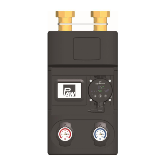
PAW HeatBloC K36E Installation And Operation Instructions Manual
Boiler charging set
Hide thumbs
Also See for HeatBloC K36E:
- Installation and operation instructions manual (18 pages) ,
- Installation and operation instruction manual (24 pages)
Table of Contents
Advertisement
Quick Links
Advertisement
Table of Contents

Subscribe to Our Youtube Channel
Related Manuals for PAW HeatBloC K36E


Summary of Contents for PAW HeatBloC K36E
- Page 1 PAW GmbH & Co. KG Böcklerstr. 11, D-31789 Hameln Phone: +49-5151-9856-0, Fax: +49-5151-9856-98 E-mail: info@paw.eu, Web: www.paw.eu Installation and Operation Instructions HeatBloC K36E - Boiler charging set DN 25 / DN 32 DN 25 DN 32 2017/01 993x03x3x-mub-en – V01...
-
Page 2: Table Of Contents
PAW GmbH & Co. KG Translation of the original instructions Böcklerstraße 11 We reserve the right to make technical changes without notice! D-31789 Hameln, Printed in Germany – Copyright by PAW GmbH & Co. KG Germany 993x03x3x-mub-en – V01 2017/01... -
Page 3: General Information
Scope of these instructions These instructions describe the installation, commissioning, function and the operation of the HeatBloC K36E DN 25 and DN 32. For other components of the installation, such as the pump, the controller or the modular distribution manifold, please observe the instructions of the corresponding manufacturer. -
Page 4: Safety Instructions
2 Safety instructions 2 Safety instructions The installation and commissioning as well as the connection of electrical components require technical knowledge commensurate with a recognised vocational qualification as a fitter for plumbing, heating and air conditioning technology, or a profession requiring a comparable level of knowledge [specialist]. -
Page 5: Product Description
The pump can be isolated by means of the ball valves and maintenance work on the pump can thus be carried out without draining the boiler circuit. You can mount the PAW HeatBloC directly onto a wall bracket or under/on a PAW modular distribution manifold. With adaptor connections, PAW HeatBloCs can also be installed on PAW distribution manifolds with other dimensions. -
Page 6: Function
3 Product description 3.2 Function K36E boiler charging set for return flow temperature maintenance of solid fuel boilers, wood firing and stove heating systems The boiler charging set prevents the temperature in the boiler from falling under the dew point, thus reducing the contamination of the boiler. - Page 7 3 Product description The boiler charging set can be mounted under/on a distribution manifold. In this system the pump exerts a pressure on the entire installation. When the overflow valve in the thermo controller is open, the pressure can be reduced via the valve.
-
Page 8: Thermo Controller
3 Product description Thermo controller The thermo controller is equipped with an overflow valve and a thermal control valve. Overflow valve In systems with a distribution manifold, the pump of the boiler charging set exerts an initial pressure on the entire installation. If the overflow valve of the thermo controller is open, the pressure can be reduced via the valve. - Page 9 3 Product description Thermal control valve The thermal control valve serves as a bypass in the startup phase. 1. If the water temperature in the boiler circuit is lower than the opening temperature of the thermal control valve, this valve is closed and thus also the line to the consumers.
- Page 10 3 Product description Change of the flow line [specialist] 1. Take off the thermometer handles (C-2, D-2) and remove the insulating front shells. 2. Take the group of fittings out of the insulating back shell. 3. Loosen the union nuts at the thermo controller (A-2).
-
Page 11: Check Valve
3 Product description Check valve The HeatBloC is equipped with a check valve (G-2) in the thermo controller (A-2). It can be opened manually. Operation During operation, the marking must be directed to "Z". The check valve is closed. ... -
Page 12: Assembly And Installation [Specialist]
4 Assembly and installation [specialist] 4 Assembly and installation [specialist] The HeatBloC K36E can be mounted on/under a PAW modular distribution manifold or on a wall bracket. The K36E is prepared for assembly under a distribution manifold DN 25 when it is delivered. - Page 13 4 Assembly and installation [specialist] Option 2: Option 3: under a PAW modular distribution directly on a wall bracket manifold. Consumer circuit Flow Return Return Flow Return Flow Return Flow Heat generator Please observe the separate and respectively corresponding instructions regarding the installation of the distribution manifold, of the mounting plate and of the wall bracket.
- Page 14 (G-3) to the wall bracket. Only for the assembly under a modular distribution manifold Mount the distribution manifold on the PAW wall bracket. You can mount the heating circuit K36E directly on the connections of the manifold. Remove the plugs in the pipe connections of the modular distribution manifold if necessary.
-
Page 15: Accessories: Cutting-Ring Compression Fitting (Not Included In The Scope Of Delivery)
5 Scope of delivery [specialist] 4.2 Accessories: Cutting-ring compression fitting (not included in the scope of delivery) The connection to the heating installation can be carried out fast, pressure-proof and without soldering if you use the optionally available compression fittings. 1. -
Page 16: Spare Parts Dn 25
5 Scope of delivery [specialist] Spare parts DN 25 Item number heating circuit Pump Item no. 45 °C 60 °C 360343WY6 360373WY6 Wilo-Yonos PARA RS 25/6-RKA E1236046 < 0.20 360343WY8 360373WY8 Wilo-Yonos PARA RS 25/7.5-RKA E1236048 < 0.21 360343WH6 360373WH6 Wilo-Stratos PICO 25/1-6 E1239625 <... -
Page 17: Spare Parts Dn 32
5 Scope of delivery [specialist] Spare parts DN 32 Item number heating circuit Pump Item no. 45 °C 60 °C 390343WY6 390373WY6 Wilo-Yonos PARA RS 30/6-RKA E1236056 < 0.20 390343WH6 390373WH6 Wilo-Stratos PICO 30/1-6 E1239630 < 0.20 390343WY10 390373WY10 Wilo-Yonos PARA HF 30/0.5-10 E12361510 <... -
Page 18: Technical Data
6 Technical data 6 Technical data K36E DN 25 (1") DN 32 (1¼") Dimensions Centre distance (1) 125 mm 125 mm Width insulation (2) 250 mm 250 mm Height insulation (3) 383 mm 441 mm Installation length (4) 408 mm 465 mm Connections Outlet (A-1, G-1) -
Page 19: Pressure Drop And Pump Characteristic Curves Dn 25
6 Technical data K36E DN 25 (1") DN 32 (1¼") Hydraulics Maximum pressure 6 bars 6 bars Maximum temperature 110 °C 110 °C value [m 6.1 Pressure drop and pump characteristic curves DN 25 Flow rate [l/h] Pressure drop and pump characteristic curves DN 32 Flow rate [l/h] 2017/01 993x03x3x-mub-en –... - Page 20 PAW GmbH & Co. KG www.paw.eu Böcklerstraße 11 Phone: +49 (0) 5151 9856 - 0 D-31789 Hameln, Germany Fax: +49 (0) 5151 9856 - 98 993x03x3x-mub-en – V01 2017/01...
Need help?
Do you have a question about the HeatBloC K36E and is the answer not in the manual?
Questions and answers