Table of Contents
Advertisement
Quick Links
www.ti.com
User's Guide
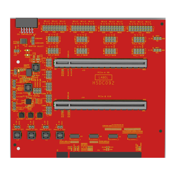
DS160PR412-421EVM Evaluation Module
The DS160PR412-421EVM evaluation module provides a complete high-bandwidth platform for evaluating the
signal conditioning features of the DS160PR412 and DS160PR421 Quad-Channel PCI Express 4.0 Linear
Redrivers. This evaluation board can be used for standard compliance testing, performance evaluation, and
initial system prototyping.
SNLU288 – DECEMBER 2020
Submit Document Feedback
ABSTRACT
Figure 1-1. DS160PR412-421EVM
Copyright © 2020 Texas Instruments Incorporated
DS160PR412-421EVM Evaluation Module
1
Advertisement
Table of Contents

Related Manuals for Texas Instruments DS160PR412-421EVM


Summary of Contents for Texas Instruments DS160PR412-421EVM
- Page 1 DS160PR412-421EVM Evaluation Module ABSTRACT The DS160PR412-421EVM evaluation module provides a complete high-bandwidth platform for evaluating the signal conditioning features of the DS160PR412 and DS160PR421 Quad-Channel PCI Express 4.0 Linear Redrivers. This evaluation board can be used for standard compliance testing, performance evaluation, and initial system prototyping.
-
Page 2: Table Of Contents
2.4 DS160PR412 and DS160PR421 Equalization Control...................... 2.5 DS160PR412 and DS160PR421 RX Detect State Machine....................5 2.6 DS160PR412 and DS160PR421 DC Gain Control......................6 2.7 DS160PR412-421EVM Global Controls ........................... 2.8 DS160PR412-421EVM Downstream Devices Control.......................8 2.9 DS160PR412-421EVM Upstream Devices Control......................2.10 Quick-Start Guide (Pin Mode)............................ -
Page 3: Introduction
Introduction 1 Introduction The DS160PR412-421EVM features two DS160PR412 and two DS160PR421 linear redrivers that can extend the transmission distance of a PCIe Gen-4 x8 bus. The EVM can be directly plugged into a PCIe slot on a server or PC motherboard using the PCIe Edge connector on the board and paired with a PCIe add-in card using one of the two PCIe connectors on the EVM. -
Page 4: Description
EQ0/ADDR Pin Level 7-Bit Address [HEX] 7-Bit Address [HEX] 0x18 0x19 0x1A 0x1B 0x1C 0x1D 0x1E 0x1F 0x20 0x21 0x22 0x23 0x24 0x25 0x26 0x27 DS160PR412-421EVM Evaluation Module SNLU288 – DECEMBER 2020 Submit Document Feedback Copyright © 2020 Texas Instruments Incorporated... -
Page 5: Ds160Pr412 And Ds160Pr421 Equalization Control
RX_DET/SCL pin of DS160PR412 and DS160PR421 provides additional flexibility to system designers to appropriately set the device in their desired mode, according to Table 2-5. SNLU288 – DECEMBER 2020 DS160PR412-421EVM Evaluation Module Submit Document Feedback Copyright © 2020 Texas Instruments Incorporated... -
Page 6: Ds160Pr412 And Ds160Pr421 Dc Gain Control
The DC gain of each channel of each device can also be set by writing to SMBus / I2C registers in Slave or Master Modes. See the DS160PR412, DS160PR421 Programming Guide for details. DS160PR412-421EVM Evaluation Module SNLU288 – DECEMBER 2020 Submit Document Feedback Copyright © 2020 Texas Instruments Incorporated... -
Page 7: Ds160Pr412-421Evm Global Controls
CLK Buffer Enable 1-2 : Disabled 2-3: Enabled JMP19 CLK Buffer Input 1-2 : CLKIN1 2-3: CLKIN0 JMP20 CLK Buffer Ref. 1-2 : Enabled 2-3: Disabled SNLU288 – DECEMBER 2020 DS160PR412-421EVM Evaluation Module Submit Document Feedback Copyright © 2020 Texas Instruments Incorporated... -
Page 8: Ds160Pr412-421Evm Downstream Devices Control
Description www.ti.com 2.8 DS160PR412-421EVM Downstream Devices Control Table 2-8 shows DS160PR412-421EVM downstream devices controls that affect DS1 and DS2 devices on the board. Table 2-8. EVM Downstream Devices Controls COMPONENT NAME FUNCTION OR DESCRIPTION 1-2: EQ0 L0 3-4: EQ0 L1... -
Page 9: Ds160Pr412-421Evm Upstream Devices Control
Description 2.9 DS160PR412-421EVM Upstream Devices Control Table 2-9 shows DS160PR412-421EVM upstream devices controls that affect US1-US2 devices on the board. Table 2-9. EVM Upstream Devices Controls COMPONENT NAME FUNCTION OR DESCRIPTION 1-2: EQ0 L0 3-4: EQ0 L1 5-6: EQ0 L2... -
Page 10: Quick-Start Guide (Pin Mode)
On JMP11 connector, place a shunt across pins 5-6 L2 for upstream device PR421_2. • On JMP14 connector, remove shunts across 1-2, 3-4, 5-6 so EQ0_ADD# pin is floating L3 for upstream device PR421_3. DS160PR412-421EVM Evaluation Module SNLU288 – DECEMBER 2020 Submit Document Feedback Copyright © 2020 Texas Instruments Incorporated... -
Page 11: Figure 2-1. Sigcon Architect Ds160Pr412-421 High Level Page
2-3. 5. Connect USB2ANY Adapter to P4 (Note that the USB2ANY Adapter is not supplied with the DS160PR412-421EVM). Install shunt on JMP17 across pins 1-2. 6. Install SigCon Architect Version 3.0.0.15 application and the DS160PR412-421 profile. 7. Plug the EVM into a PCIe x16 server motherboard slot. Ensure the motherboard is powered down before installing the EVM or configured for hot-plug operation. -
Page 12: Schematics
Schematics www.ti.com 3 Schematics Figure 3-1 through Figure 3-9 show the EVM schematics. Figure 3-1. DS160PR412 DS160PR412-421EVM Evaluation Module SNLU288 – DECEMBER 2020 Submit Document Feedback Copyright © 2020 Texas Instruments Incorporated... -
Page 13: Figure 3-2. Ds160Pr421
Schematics Figure 3-2. DS160PR421 SNLU288 – DECEMBER 2020 DS160PR412-421EVM Evaluation Module Submit Document Feedback Copyright © 2020 Texas Instruments Incorporated... -
Page 14: Figure 3-3. Configuration Headers
Schematics www.ti.com Figure 3-3. Configuration Headers DS160PR412-421EVM Evaluation Module SNLU288 – DECEMBER 2020 Submit Document Feedback Copyright © 2020 Texas Instruments Incorporated... -
Page 15: Figure 3-4. I2C Adapter Selection
Schematics Figure 3-4. I2C Adapter Selection Figure 3-5. Power SNLU288 – DECEMBER 2020 DS160PR412-421EVM Evaluation Module Submit Document Feedback Copyright © 2020 Texas Instruments Incorporated... -
Page 16: Figure 3-6. Edge Finger
Schematics www.ti.com Figure 3-6. EDGE Finger Figure 3-7. PCIe Clock DS160PR412-421EVM Evaluation Module SNLU288 – DECEMBER 2020 Submit Document Feedback Copyright © 2020 Texas Instruments Incorporated... -
Page 17: Figure 3-8. Pcie X8 Connector A
Schematics Figure 3-8. PCIe x8 Connector A SNLU288 – DECEMBER 2020 DS160PR412-421EVM Evaluation Module Submit Document Feedback Copyright © 2020 Texas Instruments Incorporated... -
Page 18: Figure 3-9. Pcie X16 Connector B
Schematics www.ti.com Figure 3-9. PCIe x16 Connector B DS160PR412-421EVM Evaluation Module SNLU288 – DECEMBER 2020 Submit Document Feedback Copyright © 2020 Texas Instruments Incorporated... -
Page 19: Pcb Layouts
PCB Layouts 4 PCB Layouts Figure 4-1 through Figure 4-6 illustrate the EVM PCB layout images. Figure 4-1. Top Layer Figure 4-2. Layer 2 SNLU288 – DECEMBER 2020 DS160PR412-421EVM Evaluation Module Submit Document Feedback Copyright © 2020 Texas Instruments Incorporated... -
Page 20: Figure 4-3. Layer 3
PCB Layouts www.ti.com Figure 4-3. Layer 3 Figure 4-4. Layer 4 DS160PR412-421EVM Evaluation Module SNLU288 – DECEMBER 2020 Submit Document Feedback Copyright © 2020 Texas Instruments Incorporated... -
Page 21: Figure 4-5. Layer 5
PCB Layouts Figure 4-5. Layer 5 Figure 4-6. Bottom Layer SNLU288 – DECEMBER 2020 DS160PR412-421EVM Evaluation Module Submit Document Feedback Copyright © 2020 Texas Instruments Incorporated... -
Page 22: Bill Of Materials
5,R26,R31,R32,R33,R34,R35,R36,R Components 37,R38,R39,R40,R41,R48,R51,R62, R65,R66,R6 R2,R5,R8,R11,R14,R17,R20,R23,R2 Panasonic Electronic ERJ-2GEJ133X 7,R28,R42,R43,R44,R49,R52,R63,R Components 68,R69,R70,R75 R3,R6,R9,R12,R15,R18,R21,R24,R2 Panasonic Electronic ERJ-2RKF5902X 9,R30,R45,R46,R47,R50,R53,R64,R Components 71,R72,R73,R76 R79,R80 4.7K Panasonic Electronic ERJ-2GEJ472X Components DS160PR412-421EVM Evaluation Module SNLU288 – DECEMBER 2020 Submit Document Feedback Copyright © 2020 Texas Instruments Incorporated... - Page 23 Keystone Electronics 9900 U1,U2 DS160PR412 Texas Instruments DS160PR412 U3,U4 DS160PR421 Texas Instruments DS160PR421 TMUX1133PWR Texas Instruments TMUX1133PWR TPS548B22RVFT Texas Instruments TPS548B22RVFT LMK00334RTVR Texas Instruments LMK00334RTVR SNLU288 – DECEMBER 2020 DS160PR412-421EVM Evaluation Module Submit Document Feedback Copyright © 2020 Texas Instruments Incorporated...
- Page 24 TI products. TI’s provision of these resources does not expand or otherwise alter TI’s applicable warranties or warranty disclaimers for TI products. TI objects to and rejects any additional or different terms you may have proposed. IMPORTANT NOTICE Mailing Address: Texas Instruments, Post Office Box 655303, Dallas, Texas 75265 Copyright © 2022, Texas Instruments Incorporated...
Need help?
Do you have a question about the DS160PR412-421EVM and is the answer not in the manual?
Questions and answers