Table of Contents
Advertisement
Available languages
Available languages
Quick Links
APPLICATION
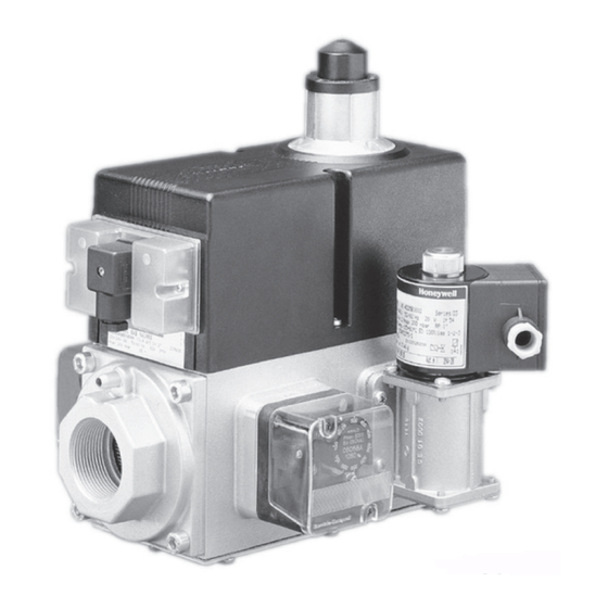
The VQ400 Series class „A" safety combination valves are
used for control and regulation of gaseous fluids in gas po-
wer burners, atmospheric gas boilers, melting furnaces,
incinerators and other gas consuming appliances.
These combination valves are available in two body sizes:
• model VQ420/25 (pipe sizes 3/4" and 1")
• model VQ440/50 (pipe sizes 1 1/2" and 2")
The 1 1/4" connection is obtained by using a DN32 flange kit
on a VQ440 body.
The features and specifications of both models are identical
(unless specified otherwise).
CLASS „A" COMBINATION VALVES
SPECIFICATION
The specifications described in this chapter are related to
the main gas valve, by-pass valve and pilot valve.
Models
VQ420/25 (DN20 and DN25)
VQ440/50 (DN40 and DN50)
NOTE: DN32 connection is obtained with a flange kit on
Dimensions
See dimensional drawings and table on page 4.
Pipe sizes
Main body: Inlet and outlet straight flange connection 3/4",
Pilot valve and vent valve: outlet 3/4" thread.
(all internal pipe thread according to ISO 7-1)
model VQ440/50
Capacity
Main body: see capacity curves on page 3.
Pilot valve and vent valve on VQ400 DN20 .. 50: as VE4020
By-pass on VQ400 DN20 .. 40:
By-pass on VQ400 DN50
(see capacity curves VE4000 Series product handbook)
Maximum operating pressure
200 or 360 mbar, depending on the model
Opening time
First valve (V1): < 1 sec.
Second valve (V2), by-pass valve and pilot valve:
fast: <1 sec.
slow: adjustable from 1 ... 30 sec.
Vent valve: <1 sec.
Closing time
First valve (V1), second valve (V2), by-pass valve, pilot valve
and vent valve: <1 sec.
Connections
model VQ420/25
•
Pressure taps at inlet and outlet flanges.
•
Optional: 1/4" plug connection for Closed Position
Indication switch (CPI) at bottom of safety valve V1.
At the main body (4) flange connections are provided to
mount either an:
•
internal by-pass valve to achieve high-low flame control
•
internal or external pilot valve
•
vent valve
•
pressure switches (Min. or Max.)
•
Valve Proving System (VPS).
Supply voltages
Line voltage: 220 ... 240 Vac, 50/60 Hz
1
VQ400 Series
INSTRUCTION SHEET
VQ440 body.
1", 1 1/4", 1 1 /2" and 2".
200 Vac, 50/60 Hz
100/110 Vac, 50/60 Hz
24 ... 28 Vdc
MU2C-0042SZ20 R0505
as VE4020
as VE4025
Advertisement
Table of Contents

Related Manuals for Honeywell VQ400 Series


Summary of Contents for Honeywell VQ400 Series
- Page 1 Indication switch (CPI) at bottom of safety valve V1. At the main body (4) flange connections are provided to mount either an: The VQ400 Series class „A“ safety combination valves are used for control and regulation of gaseous fluids in gas po- •...
- Page 2 -15 ... 60 °C " 2 Enclosure IP54 Standards and Approvals IP65 (optional, only for VQ420/25) The VQ400 Series class „A“ combination valves conform with the following EC-directives: Strainer • Gas Appliance Directive (90/396/EEC) AISI 303 steel PIN: CE-0063AR1520 Flange kits •...
-
Page 3: Capacity Curves
DN20 Vn (m /h) ∆ 40 50 60 Methane ∆v=0.64 Fig. 1. Capacity curve for VQ400 Series class „A“ combination valves INSTALLATION WARNING See installation drawing on page 4. • Turn off gas supply before installation. IMPORTANT • Disconnect power supply to the valve actuator 1. - Page 4 DIMENSIONAL DRAWINGS VQ400 SERIES 88.5 88.5 model VQ432/40/50 modular model VQ420/25 (V2 slow) model VQ432/40/50 (V2 slow) model VQ420/25 modular Table 4. Dimensions VQ400 Series (see also installation drawing) MU2C-0042SZ20 R0505...
-
Page 5: Adjustments And Final Checkout
Main gas connection flanged valves 1. Take care that dirt does not enter the gas valve during handling. 2. Remove the flanges from the valve. 3. Use a sound taper fitting with thread according to ISO 7-1 or new, properly reamed pipe free from swarf. 4. -
Page 6: Option Installation
IMPORTANT To ensure a satisfactory setting of the valve the pressure drop over the valve should be at least 10% of the supply pressure or 2.5 mbar which ever is the greatest. Fig. 5. Flow rate adjustment ( see fig. 6. and fig. 7.) 1. -
Page 7: Technische Daten
Am Hauptkörper sind (4) Flanschanschlüsse vorgesehen für DEUTSCH Anbringung: • entweder eines internen By-pass Ventil zur Erzielung ei- ner Regelung für hohe und niedrige Flamme (2-stufig) ANWENDUNG • oder eines Zündgasventil, Die Sicherheits-Kombiventile der Serie VQ400, Klasse „A“, • eines Entlüftungsventil, werden für Steuerung und Regelung von gasförmigen Brenn- •... -
Page 8: Montage
Stromverbrauch (W) (..) Ausführungen für 360 mbar Hauptventil, Serie VQ400 (siehe Tabelle 1; Seite 2) Hauptgasanschluss Zusatzventile (siehe Tabelle 2; Seite 2) 1. Achten Sie darauf, dass während der Handhabung kein Bemerkungen Schmutz in das Gasventil eindringt. additional valves = Zusatzventil 2. - Page 9 Einstellung der Öffnungsgeschwindigkeit (siehe Abb. 9.) EINSTELLUNGEN 1. Entfernen Sie die Kappe oben an der Spule, indem Sie beide Schrauben lösen. Die in diesem Kapitel beschriebenen Prozeduren betreffen 2. Führen Sie einen Schraubenzieher in den Schlitz der Jus- die Einstellvorgänge am Hauptgasventil, Zündgasventil und tierschraube ein, die sich an der Mittelachse befindet.
-
Page 10: Installazione
Dimensioni Kit flangia Vedi disegni degli ingombri e la tavola a pagina 4. Sono disponibili due tipi di flange: La prima serie di kit consiste di: 1 flangia con presa o attacco Collegamenti di pressione, 1 O-ring e 4 viti. Corpo principale: Flange d’ingresso ed uscita da 3/4", 1", 1 1/4", 1 1 /2"... - Page 11 Utilizzare cavi che possono resistere ad una temperatura ATTENTIONE ambiente di 105 °C . L’operatore ON/OFF viene fornito con un blocco terminali • Interrompere l’alimentazione del gas prima di per i collegamenti elettrici. iniziare l’installazione. Cablaggio • Scollegare l’alimentazione elettrica della valvola Si seguano le istruzioni fornite dal costruttore.
-
Page 12: Specifications
Regolazione della velocità d’apertura (vedi Fig. 9.) Modèles 1. Dopo aver svitato le due viti, togliere il coperchio dalla VQ420/25 (DN20 et DN25) parte superiore. VQ440/50 (DN40 et DN50) 2. Agire con un cacciavite sulla vite di regolazione laterale. NOTE: La connexion DN32 est obtenue avec un kit de brides 3. - Page 13 Filtre tamis 4. Effectuer un contrôle complet lorsque l’installation a été Tamis entre la bride d’entrée et le corps principal. terminée. Brides ATTENTION Il y a deux kits de brides disponibles: Le premier kit consiste en: 1 bride, 1 joint torique et 4 vis. Le deuxième kit consiste en: 1 bride, 1 joint torique, 1 filtre •...
- Page 14 Automation & Control Solutions Automation & Control Solutions Automation & Control Solutions Automation & Control Solutions Automation & Control Solutions Control Product Satronic AG Honeywell-Platz 1 CH-8157 Dielsdorf Phone: +41 1 855 22 11 Fax: +41 1 855 22 22 MU2C-0042SZ20 R0505...
Need help?
Do you have a question about the VQ400 Series and is the answer not in the manual?
Questions and answers