Advertisement
Quick Links
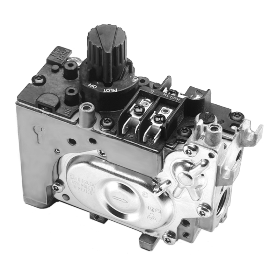
Millivolt Combination Gas Control
VS8510/VS8520
APPLICATION
The VS8510 and VS8520, millivolt combination gas
controls, are low capacity compact size millivolt operated
gas valves, see Figure 1. They are designed for use in
small gas appliances burning either LP or natural gas.
Primary appliance applications include gas fireplaces,
fireplace inserts, log sets, free standing stoves, wall
furnaces, and room space
The VS8510 and VS8520 millivolt gas valves are approved
in accordance with IAS (AGA and CGA).
® U.S. Registered Trademark
Copyright © 1997 Honeywell Inc. • All Rights Reserved
FEATURES
• For use with 750mV thermopile generator.
• VS8510 has operator and power unit powered by
750mV thermopile generator.
• VS8520 has operator powered by 750mV thermopile
and power unit powered by 30mV thermocouple.
• Vented and vent free models.
• Available with standard or high/low regulators.
• Capacity rated at 60,000 BTUH at 1" wc pressure drop.
Maximum regulation capacity is 100 BTUH and
minimum regulated capacity is 10 BTUH. All capacities
are with side inlet.
• Adjustable servo regulator maintains almost constant
gas outlet pressure over a wide range of gas supply
pressures.
• Models available with 0˚F to 175˚F (-18˚C to 79˚C),
-40˚F to 175˚F (-40˚C to 79˚C), 0˚F to 225˚F (-18˚C to
107˚C).
• Multiple inlet and output main gas connections with
NPT or BSP.
• Multiple pilot outlet and thermocouple locations.
HI/LOW
• European style inlet and outlet pressure taps.
option
• Programmed lighting sequence with safe lighting pilot
system and safety shutoff.
• Fine mesh inlet screen included optional outlet screen.
• Mutliple mounting holes can be mounted at any angle
between 0 and 90 degrees from the top upright position
(knob on top).
• Latching device interlock eliminates involuntary re-
ignition of the main burner.
• Snap-open opening characteristics.
• Compact.
• ECO (Energy Cut-Off) option.
Application ........................................................................
Features ...........................................................................
Specifications ...................................................................
Ordering Information ........................................................
Installation ........................................................................
Startup and Checkout ......................................................
Service .............................................................................
Accessories ......................................................................
VS8510/VS8520
PRODUCT DATA
Contents
1
1
2
2
5
7
12
12
68-0203
Advertisement

Related Manuals for Honeywell VS8510


Summary of Contents for Honeywell VS8510
-
Page 1: Table Of Contents
Millivolt Combination Gas Control PRODUCT DATA FEATURES • For use with 750mV thermopile generator. • VS8510 has operator and power unit powered by 750mV thermopile generator. • VS8520 has operator powered by 750mV thermopile and power unit powered by 30mV thermocouple. -
Page 2: Specifications
Honeywell, 1885 Douglas Drive North Minneapolis, Minnesota 55422-4386 In Canada—Honeywell Limited/Honeywell Limitée, 35 Dynamic Drive, Scarborough, Ontario M1V 4Z9. International Sales and Service Offices in all principal cities of the world. Manufacturing in Australia, Canada, Finland, France, Germany, Japan, Mexico, Netherlands, Spain, Taiwan, United Kingdom, U.S.A. - Page 3 VS8510/VS8520 MILLIVOLT COMBINATION GAS CONTROL Model Voltage and Capacity: See Table 2. Table 2. VS8510/VS8520 Voltage and capacity ratings. Capacity at 1” Capacity at 1” Minimum Maximum pd with Side pd with Regulated Regulated Model Operator Thermocouple Inlet Bottom Inlet...
- Page 4 Mounting support in eight locations on valve No. 10-24 screw. • Inlet on bottom and outlet on side. Option M5X 0.8 screw; cored hole on diaphragm side accepts #10-24 screw. Dimensions See Figure 2 for the dimensions of the VS8510/VS8520 Models. HI/LO REGULATOR PILOTSTAT KNOB ADJUSTMENT...
-
Page 5: Installation
VS8510/VS8520 MILLIVOLT COMBINATION GAS CONTROL Converting Between Natural and LP Gas INSTALLATION When Installing this Product... WARNING • Read these instructions carefully. Failure to follow them Fire or explosion hazard. could damage the product or cause a life threatening Can cause severe injury or death and property hazardous condition. - Page 6 VS8510/VS8520 MILLIVOLT COMBINATION GAS CONTROL 3. Thread pipe 9/16 in. into the control. Do not insert TWO IMPERFECT THREADS GAS CONTROL deeper than 3/8 in. Valve distortion or malfunction can result if the pipe is inserted too deeply. 4. Apply a moderate amount of good quality pipe...
-
Page 7: Startup And Checkout
STARTUP AND CHECKOUT GAS VALVE The Millivolt Gas Valve System has two configurations. The first configuration (VS8510) includes a gas valve, thermopile, millivolt thermostat, and a pilot burner. The thermopile drives the operator and the power unit The second configuration (VS8520) includes a gas valve, quick drop-out thermocouple, thermopile, millivolt thermostat and a pilot burner. - Page 8 2. While holding the knob down, light the pilot burner, before the lighting sequence can begin again. The continue to hold knob down until a strong flame is VS8510 drops out within three minutes. The VS8520 present (approximately 60 seconds). drops out within 30 seconds.
- Page 9 VS8510/VS8520 MILLIVOLT COMBINATION GAS CONTROL STANDING PILOT MILLIVOLT VALVE PILOT-POSITION (SAFETY/MANUAL VALVE OPEN) SERVO VENT REGULATOR SUPPLY ORIFICE SERVO MILLIVOLT OPERATOR VALVE PILOTSTAT KNOB MAIN VALVE POWER UNIT Q313 THERMOPILE ELECTRODE MAIN BURNER INTLET OUTLET Q377 PILOT BURNER CONNECT THERMOPILE...
- Page 10 VS8510/VS8520 MILLIVOLT COMBINATION GAS CONTROL STANDING PILOT MILLIVOLT VALVE ON POSITION (VALVES OPEN) SERVO VENT REGULATOR SUPPLY ORIFICE SERVO MILLIVOLT OPERATOR VALVE PILOTSTAT KNOB MAIN VALVE POWER UNIT Q313 THERMOPILE ELECTRODE MAIN BURNER INTLET OUTLET Q377 PILOT BURNER CONNECT THERMOPILE...
- Page 11 Gas Leak Test should go off and pilot should remain lit. 2. Extinguish pilot flame. The VS8510 pilot gas flow should 1. Paint the pipe connections upstream of the gas control stop within three minutes; the VS8520 pilot gas flow with rich soap and water solution.
-
Page 12: Service
VS8510/VS8520 MILLIVOLT COMBINATION GAS CONTROL • Exposure to water, dirt, chemicals and heat can damage 4. If no voltage is present, check the control circuit for the gas control and shut down the control system. proper operation. 5. If proper control system voltage is present, replace the The maintenance program should include regular checkout of gas control.
Need help?
Do you have a question about the VS8510 and is the answer not in the manual?
Questions and answers