Table of Contents
Advertisement
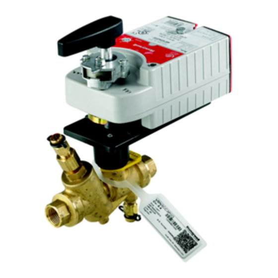
VRN Pressure Independent Control
Valves and Actuators
The VRN2 two-way pressure independent control valves
maintain constant flow of hot or chilled water with glycol
solutions up to 50% in closed-loop heating, ventilating,
and air conditioning (HVAC Division 23) systems
regardless of head pressure fluctuations above the
minimum specified pressure drop. These valve assemblies
can be used with Honeywell non-spring return or spring
return direct coupled actuators (DCA).
The built-in differential pressure regulator makes fluid
flow through the valve independent of changes in supply
pressure, eliminating "hunting" by the control system,
even at low coil flow. The pressure regulator virtually
eliminates cavitation in the valve, and decouples the
control valve from the effects of piping components such
as reducers and elbows.
Pressure independent control valves are sized to match
design coil flow regardless of coil size. VRN2 valves
eliminate the need to balance the system for proper flow,
and allow chillers to be operated at design temperature
differential for maximum efficiency at every load
condition. When used in a system with variable speed
pump drives, 3-way valves and coil bypass lines are not
Global Field Devices
required. In new construction, VRN2 valves perform better
than reverse return piping designs without the extra
materials these systems need.
Pressure-independent control requires less flow, enabling
use of smaller piping, pumps, and chillers.
• Sizes from 1/2 to 3 in. with internal (female) NPT
connections.
• Controls hot or chilled water with up to 50% glycol.
• Regulated flow rates available from 1 to 95 gpm.
• Differential pressure regulator for constant pressure
drop across valve seat.
• Positive pressure, rolling diaphragm regulator design
for flow control accuracy of ±5%.
• Equal percentage flow characteristic using patented
flow control ball insert.
• Multiple maximum flow rates available per valve size.
• Patented ball seals for low operating torque.
• Nickel-chrome plated brass or stainless steel trim.
• Choice of factory-installed actuation using
Honeywell MVN or MN/MS series direct coupled
actuators: Floating, Modulating (2-10 V), Non-Spring
Return and Spring Return.
• Spring return actuators field-configurable for
normally open or normally closed fail-safe position.
• Removable, manual operating handle to control
valve during installation or in an event of power
failure.
• Upstream Test Port for venting or pressure gauge
attachment.
• Three actuator orientations on the valve for cramped
spaces.
• Integral snubber eliminates effect of system
pressure fluctuations and entrapped air while
improving flow performance.
Application .....................................................................................
Features ..........................................................................................
Specifications ...............................................................................
Ordering Information ................................................................
Typical Specifications ............................................................... 12
Installation .................................................................................... 13
Operation And Checkout .......................................................... 18
PRODUCT DATA
Contents
1
1
2
2
38-00032-01
Advertisement
Table of Contents

Related Manuals for Honeywell VRN Series


Summary of Contents for Honeywell VRN Series
- Page 1 • Nickel-chrome plated brass or stainless steel trim. minimum specified pressure drop. These valve assemblies • Choice of factory-installed actuation using can be used with Honeywell non-spring return or spring Honeywell MVN or MN/MS series direct coupled return direct coupled actuators (DCA).
-
Page 2: Specifications
TRADELINE® Catalog or price sheets for complete ordering number. If you have additional questions, need further information, or would like to comment on our products or services, please write or phone: 1. Your local Honeywell Environmental and Combustion Controls Sales Office (check white pages of your phone directory). - Page 3 VRN PRESSURE INDEPENDENT CONTROL VALVES AND ACTUATORS Table 1. VRN Model Selection. Model Selection: Pressure Independent Control Valve Actuator Fail Position Accessories VR - Pressure Independent Control Valve C1 - 1 meter cable MVN613A0000* Leave blank = Fail in place N- Female NPT threaded 3R - NEMA MVN643A0000*...
- Page 4 VRN PRESSURE INDEPENDENT CONTROL VALVES AND ACTUATORS Table 3. Pressure Independent Valve Short Order Codes ½” – 3”. Model Selection: Control Valve Actuator Fail Position Accessories 0 - No Actuator 0 - No Actuator VRN - Pressure Independent Control Valve (valve only) or Fail in Place (FIP) 00 - None...
- Page 5 VRN PRESSURE INDEPENDENT CONTROL VALVES AND ACTUATORS Table 4. VRN Flow Rate (GPM) and Differential Pressure with Short Order Code Indicator. ΔP range Head Short Order Code Indicator Size Loss Maximum GPM Model (inch) (psi) (psi) (psi) B D E F G H J K L M N P Q R S T U 1 2 3 4 5 6 7 8 9 VRN2A 1 2 3 4 5 6 7 1 2 3 4 5 6 7...
- Page 6 VRN PRESSURE INDEPENDENT CONTROL VALVES AND ACTUATORS CLEARANCE ABOVE ACTUATOR 3/4 (19) M34967 Fig. 1. Valve Dimensions with MVN Actuator; see Table 5. Table 5. Valve Dimensions with MVN Actuator. Model Pipe Size Flow, gpm (m3/h) Dimensions in in. (mm) Weight Service Replacement S.I.
- Page 7 VRN PRESSURE INDEPENDENT CONTROL VALVES AND ACTUATORS M35993 Fig. 2. Dimensions of valves used with MN/MS actuators; see Table 6. Actuator not shown. See Figures 4 and 5 for MN/MS actuator dimensions. Table 6. Dimensions of valves used with MN/MS actuators; see Fig. 2. See Figures 4 and 5 for MN/MS actuator dimensions.
-
Page 8: Application
VRN PRESSURE INDEPENDENT CONTROL VALVES AND ACTUATORS MVN Actuator SPECIFICATIONS Actuator Type: Valve Rotational Stroke: 90° ±3°. Fail Safe Mode: Non-spring return, Fail in place Torque: 27 lb-in. (3 Nm). External Auxiliary Switches Available: No Supply Voltage: 24 Vac +20%, -15%, 24 Vdc Power Consumption: 5 VA- Modulating, 1.5 VA - Floating, 6 VA - Fast Acting SPDT Environmental Rating: NEMA2... -
Page 9: Specifications
VRN PRESSURE INDEPENDENT CONTROL VALVES AND ACTUATORS Non-Spring Return Direct Coupled Maximum Noise Rating, Driving (dBA @ 1m): 35 Actuator Rotation to Open: By switch Rotational Stroke Adjustment: Dual Integral Adj. Stops (3 degree increments) Compatible Damper Shafts: 1/4 to 1/2 in. square or 3/8 to 5/8 in. round (6 to 13 mm square or 8 to 16 mm round) Shaft Adapter Type: U-bolt clamp Supply Voltage: 24 Vac +20%, -15%, 24 Vdc... - Page 10 VRN PRESSURE INDEPENDENT CONTROL VALVES AND ACTUATORS Spring Return Direct Coupled Frequency: 50 Hz; 60 Hz Actuator Mounting: Direct Coupled Maximum Noise Rating, Holding (dBA @ 1m): 20 (no audible noise) Maximum Noise Rating, Driving (dBA @ 1m): 50 Rotation to Open: By switch Rotational Stroke Adjustment: Mechanically limited 5 degree increments Compatible Damper Shafts:...
- Page 11 VRN PRESSURE INDEPENDENT CONTROL VALVES AND ACTUATORS Table 8. Actuator Accessories and Replacement Parts. Part Number Description 5112-3R Weather Enclosure Assembly MVNAAA Replacement Valve Adaptor MVNAAL Replacement Valve Adaptor, Low Profile MVNAC7131 Replacement Cable with Terminal 1m, Modulation (RED, BLACK, WHITE) MVNAC6131 Replacement Cable with Terminal 1m, Floating (RED, BLACK, WHITE)
-
Page 12: Typical Specifications
They are designed for a medium temperature range of from 35 to 250°F, at a maximum pressure of 360 psig VRN Valve Actuator valves are to be operated with the appropriate Honeywell direct coupled actuators only. Actuator shall accept analog modulating [(0)2-10 Vdc],... -
Page 13: Installation
VRN PRESSURE INDEPENDENT CONTROL VALVES AND ACTUATORS INSTALLATION 3. Eliminate air from system. 4. Two-way valves are marked to show flow direction. IMPORTANT When installing this product... Flow arrows must point in the direction of the flow for proper operation. 1. - Page 14 VRN PRESSURE INDEPENDENT CONTROL VALVES AND ACTUATORS HANDLE (REMOVABLE) FOR MANUALLY ROTATING SHAFT** SCREWS (2)** STEM ASSEMBLY COVER** M29519A Fig. 8. Acceptable valve angle from vertical for MN and MS actuators. STEM ASSEMBLY** SCREWS (2)** BOLT** VALVE STEM COUPLER** ANTI-ROTATION BRACKET** MOUNTING PLATE**...
-
Page 15: Electrical Installation
VRN PRESSURE INDEPENDENT CONTROL VALVES AND ACTUATORS Electrical Installation PROPORTIONAL ACTUATOR 1. If necessary, remove actuator wiring cover. -10 Vdc 2. Wire actuator using Figures 11 through 19 for the -10 Vdc application required. -10 Vdc 3. Replace cover. -10 Vdc Wiring VALVES WITH FAIL IN PLACE ACTUATORS FLOATING ACTUATOR... - Page 16 VRN PRESSURE INDEPENDENT CONTROL VALVES AND ACTUATORS PROPORTIONAL/MODULATING: 0(2)...10 VDC OR 10...0(2) VDC CONTROLLER OUTPUT FLOATING ACTUATOR BLACK PROPORTIONAL ACTUATOR 24 VAC DIP SWITCH POSITION MODE WHITE 2-10V 0-10V BROWN 10-2V 10-0V BLACK 24 VAC TWO POSITION WHITE SPDT CONTROLLER POWER SUPPLY.
- Page 17 VRN PRESSURE INDEPENDENT CONTROL VALVES AND ACTUATORS ACTUATOR ACTUATOR 24 VAC 24 VAC OR + OR + 0/2 TO 10 VDC 0/2 TO 10 VDC PROPORTIONING PROPORTIONING OR N/A OR N/A CONTROLLER CONTROLLER FEEDBACK FEEDBACK – – 2-10 VDC 2-10 VDC 10-2 VDC 10-2 VDC SPDT...
-
Page 18: Operation And Checkout
VRN PRESSURE INDEPENDENT CONTROL VALVES AND ACTUATORS c. For analog control actuators either: (3) Change setting of reverse/direct-acting switch, or (4) Remount actuator on the bracket. 3. If the control scheme requires fail-safe operation, ensure that, upon removal of power, the fail position coincides with the control sequence. - Page 19 VRN PRESSURE INDEPENDENT CONTROL VALVES AND ACTUATORS temperature due to changes in fluid flow, and reducing the next larger valve size needed to satisfy design load. Do not need for the control system to constantly operate the oversize valves—reduced rangeability and may result in control portion of the valve to correct for the non-load less accurate temperature control.
- Page 20 This may cause a leak when re-assembled. Automation and Control Solutions Honeywell International Inc. 1985 Douglas Drive North ® U.S. Registered Trademark Golden Valley, MN 55422 © 2016 Honeywell International Inc. 38-00032—01 M.S. Rev. 03-16 customer.honeywell.com Printed in United States...
Need help?
Do you have a question about the VRN Series and is the answer not in the manual?
Questions and answers