Table of Contents
Advertisement
Quick Links
Advertisement
Table of Contents
Troubleshooting

Related Manuals for Berchtold OPERON B 810


Summary of Contents for Berchtold OPERON B 810
- Page 1 OPERON ® B 810 SERVICE & PARTS MANUAL...
- Page 2 OPERON B 810 surgical table. BERCHTOLD Corporation assumes no liability for table performance when used with accessories designed by others for use on the OPERON B 810 surgical table or damage to the OPERON B 810 NOTE surgical table resulting from the use of accessories designed by others.
-
Page 3: Table Of Contents
OPERON B 810 SURGICAL TABLE TABLE OF CONTENTS TABLE OF CONTENTS SPECIAL SAFETY INSTRUCTIONS........................S-1 SAFETY SYMBOLS ............................S-1 USE CONDITIONS............................S-1 POWER SUPPLY .............................. S-1 PINCH POINTS..............................S-1 LOAD CAPACITY............................S-2 PATIENT POSITIONING ..........................S-3 PATIENT ORIENTATION ..........................S-3 OPERATION .............................. - Page 4 OPERON B 810 SURGICAL TABLE TABLE OF CONTENTS PATIENT ORIENTATION..........................2-2 NORMAL ORIENTATION........................2-2 REVERSE ORIENTATION ........................2-2 PATIENT POSITIONING ..........................2-2 TABLE MOVEMENT WITH PATIENT ......................2-3 OPERATION ..............................2-3 HAND PENDANT OPERATION ........................2-4 FUNCTION PRIORITY ..........................2-5 TABLE MOVEMENT LIMITS........................
- Page 5 OPERON B 810 SURGICAL TABLE TABLE OF CONTENTS POWER SUPPLY SYSTEM ........................4-19 BATTERIES ............................. 4-19 BATTERY REPLACEMENT ......................4-20 POWER INPUT SYSTEM ........................4-21 LEFT POWER CENTER........................4-21 RIGHT POWER CENTER........................ 4-21 CONTROL PENDANTS ..........................4-22 PRIMARY HAND PENDANT ........................ 4-22 AUXILIARY HAND PENDANT......................
- Page 6 OPERON B 810 SURGICAL TABLE TABLE OF CONTENTS SUPPLY VOLTAGE ..........................6-29 PERIODIC MAINTENANCE..........................7-1 ELECTRICAL INSPECTION..........................7-1 HYDRAULIC SYSTEM OPERATION ......................7-1 GROUND CONTINUITY/LEAKAGE CURRENT ..................7-1 FLEXIBLE HYDRAULIC LINES........................7-1 HYDRAULIC FLUID LEVEL .......................... 7-1 FASTENERS AND RETAINING CLIPS......................7-2 CLAMPS AND ACCESSORIES ........................
- Page 7 MAXIMUM WEIGHT LOCATION ..................S-2 FIGURE S-2 PATIENT SAFETY WARNING LABEL ................S-6 FIGURE S-3 FUSE LABEL..........................S-6 FIGURE 1-1 OPERON B 810 SURGICAL TABLE ..................1-1 FIGURE 1-2 BASE COMPONENTS .......................1-2 FIGURE 1-3 PRODUCT IDENTIFICATION AND FUSE INFORMATION LABEL .......1-3 FIGURE 1-4 PRIMARY HAND PENDANT AND FOOTSWITCH CONNECTOR BOX......1-3...
- Page 8 OPERON B 810 SURGICAL TABLE TABLE OF CONTENTS FIGURE 4-17. BACK AND LEG CYLINDERS ..................4-10 FIGURE 4-18. KIDNEY CYLINDERS......................4-11 FIGURE 4-19. HOLLOW PLUGS AND WASHERS................. 4-11 FIGURE 4-20. SECURING HYDRAULIC LINES ..................4-12 FIGURE 4-21. CPU LOCATION ON COLUMN ..................4-13 FIGURE 4-22.
- Page 9 OPERON B 810 SURGICAL TABLE TABLE OF CONTENTS FIGURE 6-10. COM OPTIONS SETTING FORM...................6-7 FIGURE 6-11. DEVICE SETTING FORM TABS ..................6-8 FIGURE 6-12. MOTOR SETTINGS FORM ....................6-9 FIGURE 6-13. VALVE SETTINGS FORM....................6-10 FIGURE 6-14. SENSOR SETTING FORM....................6-12 FIGURE 6-15. ACCU (BATTERY) DISPLAY SETTING FORM ............6-13 FIGURE 6-16.
- Page 10 TABLE 6-1. SENSOR PARAMETERS......................6-12 TABLE 6-2. ACCU (BATTERY) SETTING PARAMETERS..............6-13 TABLE 6-3. OPERON B 810 ERROR CODES ................... 6-20 TABLE 6-4. TROUBLESHOOTING GUIDE ..................... 6-26 TABLE 6-5. LED AND TABLE STATUS FOR NO AC POWER DETECTED ........6-28 TABLE 6-6.
-
Page 11: Special Safety Instructions
OPERON B 810 SURGICAL TABLE SPECIAL SAFETY INSTRUCTIONS - IMPORTANT - THE SAFETY INSTRUCTIONS THAT FOLLOW APPEAR WITHIN THE MANUAL. READ THEM CAREFULLY BEFORE OPERATING THE UNIT AND FOLLOW INSTRUCTIONS. SPECIAL SAFETY INSTRUCTIONS PINCH POINTS SAFETY SYMBOLS WARNING — Cutting or crushing... -
Page 12: Load Capacity
OPERON B 810 SURGICAL TABLE SPECIAL SAFETY INSTRUCTIONS LOAD CAPACITY NOTE — The use of some This table has a patient lifting and articulation positioning capabilities or table NOTE capacity of 600 lb (273 kg). Positioning and accessories will put additional constraints are discussed on page S-3. -
Page 13: Patient Positioning
OPERON B 810 SURGICAL TABLE SPECIAL SAFETY INSTRUCTIONS This is accomplished by extending the PATIENT POSITIONING table’s feet by activating the FLOOR WARNING — POSSIBILITY OF LOCK function. This table is not TIPPING: Table stability may be intended for patient transport. -
Page 14: Headrest
Berchtold Corporation assumes no liability for table HOLLOW PLUGS performance when used with accessories designed by others for use on Berchtold equipment, or damage CAUTION – Do not over tighten the resulting to Berchtold equipment resulting from the hollow plugs. Over tightening can use of accessories designed by others. -
Page 15: Electromagnetic Interference
OPERON B 810 SURGICAL TABLE SPECIAL SAFETY INSTRUCTIONS life. (See drawing 306762 for correct SERVICE PROGRAM fluid designation.) CAUTION —The Service Program will allow you to set motor parameters ELECTROMAGNETIC INTERFERENCE CAUTION outside the min. and max. values of WARNING — When using the table 100 to 1000. -
Page 16: Cleaning And Disinfection
OPERON B 810 SURGICAL TABLE SPECIAL SAFETY INSTRUCTIONS CLEANING AND DISINFECTION WARNING — Unplug the power cord CAUTION — Failure to thoroughly before cleaning the table if cleaning dry the surface after cleaning may WARNING CAUTION liquids will be used near the power result in rust. -
Page 17: General Information
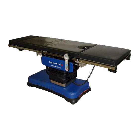
GENERAL DESCRIPTION A hand-held control pendant is used to control table The Berchtold OPERON B 810 surgical table is a positions. remote controlled, full-function design offering a high level of patient positioning and imaging The tabletop is divided into the following sections flexibility to the surgical team. -
Page 18: Power Supply
OPERON B 810 SURGICAL TABLE GENERAL INFORMATION POWER SUPPLY electronics and pump motor are isolated from the power supply and the batteries, regardless of the WARNING — Repeated breaker pendant used. tripping or fuse replacement may WARNING indicate a ground fault or overload When the charge indicator lamp near the power cord condition. -
Page 19: Floor Lock System
OPERON B 810 SURGICAL TABLE GENERAL INFORMATION In addition to the fuses, the ON/OFF switch See FIGURE 1-2 for the fuse locations. See serves as a circuit breaker with a 20 Amp rating. FIGURE 1-3 for the product identification and... -
Page 20: Primary Hand Pendant Indicators
OPERON B 810 SURGICAL TABLE GENERAL INFORMATION Primary Hand Pendant Indicators See FIGURE 1-5 for the location of the indicators 1. Aux. Pendant (amber) — Auxiliary hand pendant is active. The primary hand pendant will still be enabled if the auxiliary hand pendant is active. -
Page 21: Primary Hand Pendant Functions
OPERON B 810 SURGICAL TABLE GENERAL INFORMATION Primary Hand Pendant Functions NOTE — If AC power is not present, the auto-shutdown feature will turn the NOTE WARNING — The primary hand pendant control pendant off after about 120 is configured for normal patient WARNING minutes of non-use. -
Page 22: Footswitch (Optional)
OPERON B 810 SURGICAL TABLE GENERAL INFORMATION FOOTSWITCH (OPTIONAL) A footswitch control is available for procedures where the surgeon is normally seated at the pelvic end of the patient (FIGURE 1-7). Footswitch functions include: • Trendelenburg/Reverse Trendelenburg • Tilt Left/Tilt Right •... -
Page 23: Auxiliary Hand Pendant
OPERON B 810 SURGICAL TABLE GENERAL INFORMATION AUXILIARY HAND PENDANT CAUTION — The auxiliary hand The yellow auxiliary hand pendant (FIGURE 1-10) is pendant does not have the following CAUTION located in the auxiliary hand pendant control drawer functions: FLEX, CHAIR, RETURN in the head end of the base (FIGURE 1-11). - Page 24 Leg Section 105°, Back Section 80° relative to the Seat Section, which may be up to 30° in the Trendelenburg position. Load Capacity: Lifting and Articulation 600 lbs. (273 kg) If you need assistance, call Berchtold Technical Service at 800-243-5135. Rev. 1 70-000-0027 1 - 8...
-
Page 25: Operating Instructions
7. Column shields to base cover Due to the variety of table positions attainable with 8. Base to floor the OPERON B 810 table, pinch or crushing points 9. Floor feet to base exists (FIGURE 2-1). The OR staff must be trained to 10. -
Page 26: Patient Orientation
OPERON B 810 SURGICAL TABLE OPERATING INSTRUCTIONS The patient lifting and articulation capacity is 600 lbs (273 kg). This means that a 600 lb patient can be moved into any of the standard procedural positions. PATIENT ORIENTATION WARNING — Before... -
Page 27: Operation
OPERON B 810 SURGICAL TABLE OPERATING INSTRUCTIONS WARNING — The table should not be used to transport a patient over a WARNING long distance. This procedure is only meant for repositioning the table in the surgical suite. Certain ENT, Neuro, and Ortho procedures require that the table be moved after anesthetizing the patient. -
Page 28: Hand Pendant Operation
OPERON B 810 SURGICAL TABLE OPERATING INSTRUCTIONS charging will occur whether the ON/OFF switch on To operate any hand pendant function, press and hold the base is in the ON or OFF position. The table can the button for the action desired. If you press the floor... -
Page 29: Function Priority
The software controls limit the functions described in function is operating, the function will stop. To Table 2-1. If the Operon B 810 table is positioned restart the function, you must release the function according to “Position of Function”, the software button and press it again. -
Page 30: Table 2-1. Software-Controlled Limits
OPERON B 810 SURGICAL TABLE OPERATING INSTRUCTIONS TABLE 2-1. SOFTWARE-CONTROLLED LIMITS Position of Function Resulting Function Limit Back Section raised over 26° Kidney elevator cannot be operated Limits Back section to maximum of 26° above horizontal Any raising of the kidney elevator ±... -
Page 31: User-Controlled Limits
OPERON B 810 SURGICAL TABLE OPERATING INSTRUCTIONS User-Controlled Limits locking mechanism is not engaged. CAUTION — Watch the table at all times while performing multiple CAUTION articulations. Stop table movements before collisions occur. Failure to do so could result in damage to the table. -
Page 32: Removable Leg Section
OPERON B 810 SURGICAL TABLE OPERATING INSTRUCTIONS REMOVABLE LEG SECTION Seat Section Section WARNING — Failure to securely lock the leg section into place may WARNING result in patient injury. Always check the retention of the leg section upon Latches installation. -
Page 33: Figure 2-11 Footswitch
OPERON B 810 SURGICAL TABLE OPERATING INSTRUCTIONS NOTE — To avoid inadvertent actuation, the footswitch should be NOTE disconnected for procedures that do not require its use. Table Up/ The footswitch will not operate if the red battery Table Down... -
Page 34: Backup Instructions
OPERON B 810 SURGICAL TABLE BACKUP INSTRUCTIONS BACKUP INSTRUCTIONS NOTE — When using the auxiliary It is highly recommended that all operators become hand pendant, press and hold the familiar with the following backup instructions and button while operating the foot with the operation of the auxiliary hand pendant and pump. -
Page 35: Principles Of Operation
(Column Cylinder Schematic), and damage. Figure 5-1(C8 Hydraulic Schemati), for the hydraulic system schematics. CAUTION – The hydraulic system on the OPERON B 810 surgical table Hydraulic Power Unit CAUTION contains micro-hydraulic valves, A hydraulic pump, driven by an electric motor, is the which are very sensitive to primary source of hydraulic power. -
Page 36: Column Manifold
OPERON B 810 SURGICAL TABLE PRINCIPLES OF OPERATION • Column Manifold Back cylinders • Leg cylinders A manifold on the main lift column provides • Kidney cylinders hydraulic fluid to the following cylinders (FIGURE 4-2): Table Top Distribution Block A distribution block mounted above the column •... -
Page 37: Floor Lock Manifolds
OPERON B 810 SURGICAL TABLE PRINCIPLES OF OPERATIONS Floor Lock Manifolds individual cylinders that operate the foot jacks (FIGURE 4-5). One manifold controls the floor lock system (FIGURE 4-4). Located in the foot left section of the The manifold contains no field replaceable parts. It base, the foot lock manifold directs fluid to the must be replaced as a complete unit. -
Page 38: Floor Lock System Operation
OPERON B 810 SURGICAL TABLE PRINCIPLES OF OPERATION LEDs on the extension board will turn on and off 11. When P2 closes, a signal is sent to the controller to indicate movement of the locks. that the feet are locked, illuminating the lock LED on the pendant, and de-energizing the pump 8. -
Page 39: Floor Lock Quick Disconnect
OPERON B 810 SURGICAL TABLE PRINCIPLES OF OPERATIONS Pull back Q u i c k D i s c o n n e c t Push in Pull back Push in FIGURE 4-7. FLOOR LOCK QUICK DISCONNECT Manifold Valve Description integrated return throttles (A and B). -
Page 40: Manifold Valve Operation
OPERON B 810 SURGICAL TABLE PRINCIPLES OF OPERATION TABLE 4-1 MANIFOLD VALVE OPERATING SPECIFICATIONS Parameter Range Operating Pressure Up to 3626 psi (250 bar) depending on flow rate Flow Rate 61 in. /min (3 dm /min) maximum Ambient Temperature -22 °F to +212 °F (-30 °C to +100 °C) Pressure Medium Temperature -7 °F to +176 °F (-20 °C to +80 °C) -
Page 41: Figure 4-9. Column Cylinder Schematic
OPERON B 810 SURGICAL TABLE PRINCIPLES OF OPERATION FIGURE 4-9. COLUMN CYLINDER SCHEMATIC TABLE 4-2 COLUMN SOLENOIDS Function Solenoid Valve Side Tilt Up Tilt Down Trendelenburg Reverse Trendelenburg Height Up Height Down Kidney Up Kidney Down Back Up Back Down... -
Page 42: Operation
Tilt Left and Right Tilt right is achieved by solenoid Y12 retracting the tilt cylinder. This pulls the right side of the table BERCHTOLD recommends that the tilt cylinders not down. be replaced by the end user because of the risk of contamination entering the hydraulic system. -
Page 43: Figure 4-13. Manifold And Solenoids
OPERON B 810 SURGICAL TABLE PRINCIPLES OF OPERATION BERCHTOLD recommends that the Trendelenburg The back and leg cylinders are in parallel; the kidney cylinder not be replaced by the end user because of cylinders are in series. the risk of contamination entering the hydraulic The left and right kidney cylinders are also different system.. -
Page 44: Figure 4-15. Left Side Frame Cylinders
OPERON B 810 SURGICAL TABLE PRINCIPLES OF OPERATION Leg Cylinder Kidney Switch Kidney Cylinder Back Cylinder FIGURE 4-15. LEFT SIDE FRAME CYLINDERS Leg Cylinder Kidney Cylinder Back Cylinder FIGURE 4-16. RIGHT SIDE FRAME CYLINDERS FIGURE 4-17 and FIGURE 4-18 show cylinders the same. -
Page 45: Hollow Plugs And Seals
OPERON B 810 SURGICAL TABLE PRINCIPLES OF OPERATION Left Kidney Cylinder Right Kidney Cylinder FIGURE 4-18. LEFT AND RIGHT KIDNEY CYLINDERS HOLLOW PLUGS AND SEALS 8mm plugs and seals. All other hydraulic fittings use 10mm hollow plugs and seals. Hydraulic lines are secured to cylinders and... -
Page 46: Hollow Plug Torque Specifications
Washers FIGURE 4-20. SECURING HYDRAULIC LINES Hollow Plug Torque Specifications HYDRAULIC FLUID The OPERON B 810 Surgical TableC8 hydraulic CAUTION – Do not over tighten the system uses BP Energol HLP-HM 32 (or ARAL hollow plugs. Over tightening can CAUTION VITAM DE 32) hydraulic fluid (see Drawing 306762 cause the seals to deform and leak. -
Page 47: Electrical System
230 VAC components. CPU board. Its primary function is to route input and output signals between the CPU and the table’s The OPERON B 810 electrical system schematics sensors and actuators. (wiring diagrams) are provided in 2 sections. The CPU and Auxiliary boards are located on the left FIGURE 5-2 (including 4 detail sheets) shows the side of the column (FIGURE 4-21). - Page 48 OPERON B 810 SURGICAL TABLE PRINCIPLES OF OPERATION J1 (K9 cable to connector board) J2 (Power in/out - see Figure 5-2) NOTE: CPU Board (Shown without Auxiliary Board for Clarity) J4 (Hydraulic motor power) J5 (K9 cable to Aux. board J4) J6 (K11 cable to Aux.
-
Page 49: Connector Board
OPERON B 810 SURGICAL TABLE PRINCIPLES OF OPERATION TABLE 4-4 CPU POWER CONNECTORS Harness Part Number Number Routing Signal J8-1 to kidney switch & slide J4-1 24V+ 307029 (P/O) sensor J4-2 Common 306559 Extension board J3 to slide J2-1 24V Power... -
Page 50: Extension Board
OPERON B 810 SURGICAL TABLE PRINCIPLES OF OPERATION Connector Board Footswitch Connection RS 232 Connection Hand Pendant Connection FIGURE 4-24. CONNECTOR BOARD Extension Board 4-25). The wiring diagrams and the electrical schematic on page 5-2 (et seq.) provide additional The extension board is located at the base of the information on these connections. -
Page 51: Tilt And Trendelenburg Sensors
OPERON B 810 SURGICAL TABLE PRINCIPLES OF OPERATION An auxiliary pendant drawer switch provides power to the auxiliary pendent when the drawer is opened. Slide Sensor Slide Sensor Guide Pin Slide Screw Slide Sensor Slide Motor Trendelenburg Sensor Tilt Sensor FIGURE 4-26. -
Page 52: Kidney Switch
OPERON B 810 SURGICAL TABLE PRINCIPLES OF OPERATION FIGURE 4-27. SLIDE SENSOR Kidney Switch A signal of 2.5 volts indicates that the kidney elevator is up. A signal of 4.5 volts indicates that it is The kidney switch is mounted on a bracket on the left down. -
Page 53: Power Supply System
OPERON B 810 SURGICAL TABLE PRINCIPLES OF OPERATION Power Supply System The power supply/charger assembly will provide power to the table if the batteries are not installed. It The power supply system is made up of 3 main also charges the batteries. -
Page 54: Battery Replacement
OPERON B 810 SURGICAL TABLE PRINCIPLES OF OPERATION Battery Replacement 5. Disconnect the red cable from the positive terminal of the right-hand battery (FIGURE 4- Do this to replace the batteries: 32). WARNING – Even a “dead” battery Negative Termina... -
Page 55: Power Input System
OPERON B 810 SURGICAL TABLE PRINCIPLES OF OPERATION Power Input System The power input system is made up of 2 power centers at the head of the table (FIGURE 4-33). O FF Auxiliary Hand Control Right Power Center Storage Drawer FIGURE 4-33. -
Page 56: Control Pendants
OPERON B 810 SURGICAL TABLE PRINCIPLES OF OPERATION The charge indicator LED illuminates green when charging. The indicator should always be illuminated AC is applied to the table and the batteries are if AC is applied. AC Fuse Drawer AC Fuses... -
Page 57: Auxiliary Hand Pendant
OPERON B 810 SURGICAL TABLE PRINCIPLES OF OPERATION Auxiliary Hand Pendant The auxiliary hand pendant is a backup pendant for use in case of a primary hand pendant problem, or a power problem that disables the main electric pump Auxiliary Hand Pendant and the primary hand pendant. -
Page 58: Base, Column, And Top Electrical Connections
OPERON B 810 SURGICAL TABLE PRINCIPLES OF OPERATION Base, Column, and Top Electrical The figures listed in TABLE 4-8 identify the Connections locations of the electrical connections in the base, on the column, and in the top of the table. - Page 59 OPERON B 810 SURGICAL TABLE PRINCIPLES OF OPERATION J10-2 J11-1 Left (DC) AC Mains Right (AC) (Pendant Fuse) DC Pump Fuse) Power Center Ground Power Center Connection Connection FIGURE 4-39. BASE HEAD-END WIRING CONNECTIONS Battery Series Connection Auxiliary Pendant (J9-1)
- Page 60 OPERON B 810 SURGICAL TABLE PRINCIPLES OF OPERATION Terminal Strip for Transformer AC Mains Battery Battery Charger (J2P2) AC Power Center and (L-N-G) (J1/P1) Connector Transformer Connections Connector Connector (See FIGURE 5-3) FIGURE 4-42. BASE FOOT END RIGHT WIRING CONNECTIONS...
-
Page 61: Mechanical Slide System
OPERON B 810 SURGICAL TABLE PRINCIPLES OF OPERATION Column Ground Connection Hydraulic Motor Power Connector (J4-1 (Harness K6 [306547]/P4-1) FIGURE 4-45. COLUMN HEAD SIDE CONNECTIONS Leg and Back Sensor Connector (P7-2 [to J7-2]) RS 232 Connector (P1CB [to J1CB] Harness K9 [306550]) FIGURE 4-46. - Page 62 OPERON B 810 SURGICAL TABLE PRINCIPLES OF OPERATION Motor Assembly Cover Slide Screw Guard Slide Screw Gearing Motor and Drive Belt Slide Sensor Guide Pin Motor Vibration Isolation Assembly Mounts Mount to Frame FIGURE 4-47. SLIDE MECHANISM COMPONENTS Rev. 1...
-
Page 63: Timing Belt Testing And Adjustment
OPERON B 810 SURGICAL TABLE CIRCUIT DIAGRAMS Timing Belt Testing and Adjustment If necessary, do this to adjust the tensioning: Do the following to test the tensioning of the timing 1. Loosen both tensioning adjustment screws under belt: the drive belt. -
Page 64: Circuit Diagrams
OPERON B 810 SURGICAL TABLE SERVICE PROGRAM CIRCUIT DIAGRAMS The following pages contain the hydraulic and electrical schematics for the Operon B 810 Surgical Table: • Figure 5-1, C8 Hydraulic Schemati, see page 5-2 • Figure 5-2, Wiring Diagram, see page 5-3 •... - Page 65 OPERON B 810 SURGICAL TABLE SERVICE PROGRAM FIGURE 5-1. C8 HYDRAULIC SCHEMATIC Rev. 1 70-000-0027...
-
Page 66: Service Program
OPERON B 810 SURGICAL TABLE SERVICE PROGRAM FIGURE 5-2. WIRING DIAGRAM 70-000-0027 Rev. 1... - Page 67 OPERON B 810 SURGICAL TABLE SERVICE PROGRAM FIGURE 5-3. WIRING DIAGRAM: SHEET 1 DETAIL Rev. 1 70-000-0027...
- Page 68 OPERON B 810 SURGICAL TABLE SERVICE PROGRAM WIRING DIAGRAM: SHEET 2 DETAIL 70-000-0027 Rev. 1...
- Page 69 OPERON B 810 SURGICAL TABLE SERVICE PROGRAM WIRING DIAGRAM: SHEET 3 DETAIL Rev. 1 70-000-0027...
- Page 70 OPERON B 810 SURGICAL TABLE SERVICE PROGRAM WIRING DIAGRAM: SHEET 4 DETAIL 70-000-0027 Rev. 1...
- Page 71 OPERON B 810 SURGICAL TABLE SERVICE PROGRAM BASE WIRING DIAGRAM Rev. 1 70-000-0027...
-
Page 72: Introduction
OPERON B 810 SURGICAL TABLE SERVICE PROGRAM SERVICE PROGRAM the sensors, and the processors compare the signals to ensure that they are identical. Each of the processors calculates the action required to comply with signals INTRODUCTION from the hand pendants or foot switch, but only one The service program is used both to set table of the microprocessors—designated the active... -
Page 73: How To Use The Service Program
RS 232 Connector FIGURE 6-2. PC CONNECTION Launch the Service Program If you do not have the OPERON B 810 Service Program installed on your laptop computer, contact Berchtold Technical Service for instructions. 1. Double click the service program icon on the computer’s desktop. - Page 74 OPERON B 810 SURGICAL TABLE SERVICE PROGRAM SERV indicator lights when a system error occurs: Contact Berchtold Service REV indicator lights when the table is set for Reverse operation DWR Indicator lights when auxiliary hand pendant drawer is open A fully functional image of the pendant...
-
Page 75: The Hand Pendant Graphic
OPERON B 810 SURGICAL TABLE SERVICE PROGRAM The hand pendant graphic and .each of the menu you know that the physical pendant or wiring options are explained below. needs to be replaced. In other words, the failure of the table to perform some function is related... -
Page 76: View Menu
OPERON B 810 SURGICAL TABLE SERVICE PROGRAM View Menu The View menu offers you two choices: Save File Button 1. Options • Selecting this option brings up the COM Clicking the Save File button results presents a setting form. standard Windows File Save screen (Figure 6-8). -
Page 77: Print System Settings Button
OPERON B 810 SURGICAL TABLE SERVICE PROGRAM The print system setting button prints the contents of a file or screen form to your Windows default printer. Print System Settings Button FIGURE 6-9. SYSTEM SETTINGS SCREEN Rev. 1 70-000-0027... -
Page 78: Com Button
OPERON B 810 SURGICAL TABLE SERVICE PROGRAM 4. Select the number of Stop bits to be used to separate data bits. Your choices are: COM Button • • Clicking the COM button causes the COM Options • setting form to appear (Figure 6-10). - Page 79 OPERON B 810 SURGICAL TABLE SERVICE PROGRAM NOTE: — The values shown in the illustration may not match those for NOTE your table. FIGURE 6-11. DEVICE SETTING FORM TABS Rev. 1 70-000-0027...
-
Page 80: Motor Tab
Motor Tab This is the percentage of motor’s power used during the movement. The amount of power The Motor tab allows you to set speed at which the applied equates directly to the speed with which table will perform the various movements (Figure 6- the motion is performed. -
Page 81: Valve Tab
OPERON B 810 SURGICAL TABLE SERVICE PROGRAM Valve Tab CAUTION —The Service Program will allow you to set valve parameters The valve tab allows you to control the amount of CAUTION outside the min and max range of 100- time that the hydraulic valves open before the motor 300MSec. - Page 82 OPERON B 810 SURGICAL TABLE SERVICE PROGRAM a failure to operate. Always double NOTE — Do not set the Zero Position check your settings before clicking on by typing in a value. To be accurate, NOTE “Save Parameters”. the Zero Position must be measured and set by the parameter’s sensor,...
- Page 83 OPERON B 810 SURGICAL TABLE SERVICE PROGRAM Trendlenburg Back 2,733 Slide Height FIGURE 6-14. SENSOR SETTING FORM TABLE 6-1. SENSOR PARAMETERS Name Max. Angle Min. Angle (Deg.) (Deg.) Tilt Trend Back Legs -105 Slide **118 **-90 NOTE — All Sensor (Status) values must be between 0.100 and 4.900 V (at extreme positions). If NOTE they are outside of this range (calculated by angle and ratio) the table will not move.
-
Page 84: Accu Tab
OPERON B 810 SURGICAL TABLE SERVICE PROGRAM ACCU Tab voltage value shows the charge as a percentage of total capacity. These are display values based on The ACCU (accumulator) tab sets the battery power CPU readings; they cannot be changed in the field. -
Page 85: Movements Tab
OPERON B 810 SURGICAL TABLE SERVICE PROGRAM • Movements Tab The leg section will lower 5 degrees (reverse Trendelenburg) and stop. The Movements button lets you select how the table • Etc. moves in response to the Return-To-Level, Flex, and If you release the button before the articulation has Chair buttons on the hand pendant. - Page 86 OPERON B 810 SURGICAL TABLE SERVICE PROGRAM FIGURE 6-16. MOVEMENTS SETTING FORM Table Info Tab The information on this tab is display only. It cannot be changed by the technician in the field. The “Save” button on this form is not active.
-
Page 87: System Info Button
OPERON B 810 SURGICAL TABLE SERVICE PROGRAM • Sensors The Sensors selection has a number of table info subordinate selections that you can select from a System info Button fly out menu. To get the menu list, click on the word “Sensors”. - Page 88 OPERON B 810 SURGICAL TABLE SERVICE PROGRAM • The error codes remain in the Service Program’s Errors database as a part of the table’s history. When you check ( ) the Errors box on the Read Info list, the last 100 error codes recorded by the •...
-
Page 89: Cycle Test Button
OPERON B 810 SURGICAL TABLE SERVICE PROGRAM additional options that will flyout when your cursor passes over them: Cycle Test Button • Kidney 8 Down — Up • Slide 8 Forward — Reverse The cycle test button is inoperative in the customer •... - Page 90 OPERON B 810 SURGICAL TABLE SERVICE PROGRAM NOTE — The Load File and Save File commands read and write files from NOTE and to the computer that the Service Program is operating from. Because of this, your load and save options include your floppy, CD, and other media drives.
-
Page 91: Cpu Error Codes
OPERON B 810 SURGICAL TABLE SERVICE PROGRAM CPU ERROR CODES For errors where no solutions are suggested, you can use the error name and description to determine The CPU is programmed to store error codes for a additional diagnostic steps that can be used to series of specific errors. - Page 92 OPERON B 810 SURGICAL TABLE SERVICE PROGRAM Error Reaction Description Solution Motor “current Continue Amperage exceeds expected current draw • Locate and eliminate feedback” fault from Motor (Expected maximum is 14.3 short circuit. amps) Motor short circuit, Motor disconnected, • Connect motor.
- Page 93 OPERON B 810 SURGICAL TABLE SERVICE PROGRAM Error Reaction Description Solution • Connect sensor. Sensor-6 Fault Continue Sensor disconnected, wiring broken, short • Identify and replace (Kidney) circuit broken wiring. • Locate and remove cause of short circuit. • Connect sensor.
- Page 94 OPERON B 810 SURGICAL TABLE SERVICE PROGRAM Error Reaction Description Solution • Connect valve. Valve-7 fault Continue Valve disconnected, wiring broken, short • Identify and replace (TREND) circuit, damaged solenoid coil broken wiring. • Locate and remove cause of short circuit.
- Page 95 OPERON B 810 SURGICAL TABLE SERVICE PROGRAM Error Reaction Description Solution • Connect valve. Valve-14 fault Continue Valve disconnected, wiring broken, short • Identify and replace (KIDNEY UP) circuit, damaged solenoid coil broken wiring. • Locate and remove cause of short circuit.
-
Page 96: Troubleshooting
OPERON B 810 SURGICAL TABLE SERVICE PROGRAM • TROUBLESHOOTING If possible, duplicate the actions that led to the problem and try to get the same results. NOTE – It is assumed that personnel 2. Use the information in this manual, your... -
Page 97: Table 6-4. Troubleshooting Guide
OPERON B 810 SURGICAL TABLE SERVICE PROGRAM TABLE 6-4. TROUBLESHOOTING GUIDE Problem Action Loss of main AC electrical power, If battery indicator is green or yellow, no action is required. The batteries indicated by the charging indicator are charged. being OFF. -
Page 98: Batteries And Charge Indicators
OPERON B 810 SURGICAL TABLE SERVICE PROGRAM Problem Action The pump motor functions, but no Check the primary pendant’s fuse (F5), in the left power center (Figure 6- sections move when activated. 20). Replace if blown. Use the Service Program to check for over current conditions at solenoids. -
Page 99: Ac Detected
LED level. See TABLE 6-6 for AC detected conditions as defined in the Operon B 810 product function information. specification. The latter part of the operation may 6-28 Rev. -
Page 100: Electrical Parameters
OPERON B 810 SURGICAL TABLE SERVICE PROGRAM TABLE 6-6. LED AND TABLE STATUS FOR AC POWER DETECTED LED Color Voltage Range Main Pendant Pump Motor Auxiliary Pendant Green Above 90% Functional Functional Functional Yellow Below 90% Functional Functional Functional Above 30%... -
Page 101: Periodic Maintenance
OPERON B 810 SURGICAL TABLE PERIODIC MAINTENANCE PERIODIC MAINTENANCE operation. TABLE 7-1 lists the minimum requirements to maintain the table in a ready Regularly scheduled preventive maintenance and condition. inspection is essential for continued reliable TABLE 7-1. RECOMMENDED MAINTENANCE SCHEDULE... -
Page 102: Fasteners And Retaining Clips
Doing so can cause the disinfectant and wipe dry. NOTE fluid to leak out of the breather cap. NOTE — The Operon B 810, with all covers installed, is splash proof in NOTE accordance with the IPX4 standard... -
Page 103: Removing Stains
OPERON B 810 SURGICAL TABLE PERIODIC MAINTENANCE REMOVING STAINS Pads may be cleaned with either phenolic or quaternary type disinfectants in concentrations Special cleaning is required to remove stubborn recommended by the manufacturer. Disinfectants stains such as plaster or blood that was left on the applied at full concentration or in highly concentrated surfaces for a long period of time. -
Page 104: Parts
OPERON B 810 SURGICAL TABLE PARTS THIS PAGE INTENTIONALLY BLANK Rev. 1 70-000-0027... -
Page 105: Introduction
The drawings for repair parts for the OPERON B by size and type. Some bills-of-material call for the 810 table may be obtained by calling BERCHTOLD use of thread lock compound for some fasteners. (800) 243-5135 Engineering Dept. Due to various... - Page 106 OPERON B 810 SURGICAL TABLE PARTS Drawing Page Number Description Number 304297 Assembly, Kidney Linkage, Right 8-19 304299 Assembly, Cylinder, Kidney (36mm stroke) 8-20 304491 Assembly, Cylinder, Kidney (30mm stroke) 8-21 304121 Assembly, Back Section (Two Sheets) 8-22 304120 Assembly, Leg Section (Two Sheets)
- Page 107 OPERON B 810 SURGICAL TABLE PARTS R EVISIO N S R EV. D ESC R IPT IO N EC O # D AT E R ELEASE 20609 02/04/ 04 306906 WAS 306915 20612 02/10/ 04 R ED U C E Q T Y O F 304874, ILLU S T EN SIO N ER C H G...
- Page 108 OPERON B 810 SURGICAL TABLE PARTS REVISIONS REVISIONS REV. REV. DESCRIPTION DESCRIPTION ECO# ECO# DATE DATE RELEASE RELEASE 20682 20682 01/03/05 01/03/05 NOTES: NOT SHOWN: • ALL HOSES • LEG CYLINDERS • BACK CYLINDERS • KIDNEY CYLINDERS SYSTEM IS SHIPPED CLOSED FROM MANUFACTURER...
- Page 109 OPERON B 810 SURGICAL TABLE PARTS 70-000-0027 Rev. 1...
- Page 110 OPERON B 810 SURGICAL TABLE PARTS Rev. 1 70-000-0027...
- Page 111 OPERON B 810 SURGICAL TABLE PARTS REVISIONS REV. DESCRIPTION ECO# DATE RELEASE 20683 12/07/04 NOTE: 1. DO NOT USE TERMINALS IN ITEM 11 (SUPPLIED WITH FUSE HOLDER) PART ITEM NO. DESCRIPTION Default/QTY. NUMBER 304368 HOUSING, POWER CENTER, LEFT 304370 DOOR, FUSE...
- Page 112 OPERON B 810 SURGICAL TABLE PARTS REVISIONS REV . DESCRIPTION ECO# DATE RELEASE 03/17/05 VIEW ITEM NO. PART NUMBER DESCRIPTION 6/QTY . 304373 ASSEMBLY , INTERIOR FRAME, LEFT 304091 RAIL, SECTION LEFT 304805 ASSEMBLY , PIVOT LEG SECT, LEFT 306418 SCR, FLT HD, SOC, M8-1.25X45, DA...
- Page 113 OPERON B 810 SURGICAL TABLE PARTS REVISIONS REV . DESCRIPTION ECO# DATE RELEASE 03/17/05 BERCHTOLD Corp. 1950 Hanahan Rd. Charleston, SC 29406 ASSY, SUPPORT, LEFT 306992 70-000-0027 Rev. 1...
- Page 114 OPERON B 810 SURGICAL TABLE PARTS REVISIONS REV. DESCRIPTION ECO# DATE RELEASE 20676 06/17/04 (REF) (REF) (SEE BACK LINK. ASSY. SH.2) NOTES: 1) TORQUE 11 TO 12 FT-LBF. 2) APPLY A BEAD OF BLACK SIL ICONE AROUND LOWER EDGE OF SEAL AND INSERT INTO CHANNEL.
- Page 115 OPERON B 810 SURGICAL TABLE PARTS REVISIONS REV. DESCRIPTION ECO# DATE RELEASE 20676 06/17/04 KIDNEY LINAGE ASSEMBLY BACK LINKAGE AND LEG CYLINDER REMOVED SEE SECT B-B 43 99 AND ASSEMBLED VIEW BELOW SEE SECTION B-B INSERT BETWEEN ITEMS 1 AND 17 (ALSO SEE DETAIL "C"...
- Page 116 OPERON B 810 SURGICAL TABLE PARTS BERCHTOLD Corp. BERCHTOLD Corp. Rev. 1 70-000-0027 8-12...
- Page 117 OPERON B 810 SURGICAL TABLE PARTS B E R C H T O L D C o r p . 70-000-0027 Rev. 1 8-13...
- Page 118 OPERON B 810 SURGICAL TABLE PARTS BERCHTOLD Corp. BERCHTOLD Corp. Rev. 1 70-000-0027 8-14...
- Page 119 OPERON B 810 SURGICAL TABLE PARTS REVISIONS REV. DESCRIPTION ECO# DATE RELEASE 20834 03/23/05 THIS ROD END TO BE ALIGNED WITH PORTS WHEN TIGHTENED LEAVE LOOSE UNTIL FINAL ASSY APPLY LOCTITE AND TIGHTEN ASSEMBLE TIGHT ROD END, SPACER, JAM NUT 44.00...
- Page 120 OPERON B 810 SURGICAL TABLE PARTS B E RCHTO LD Corp. B E RCHTO LD Corp. Rev. 1 70-000-0027 8-16...
Need help?
Do you have a question about the OPERON B 810 and is the answer not in the manual?
Questions and answers