Sign In
Upload
Manuals
Brands
Berchtold Manuals
Medical Equipment
OPERON B 810
Berchtold OPERON B 810 Manuals
Manuals and User Guides for Berchtold OPERON B 810. We have
2
Berchtold OPERON B 810 manuals available for free PDF download: Service Parts, Installation & Operating Manual
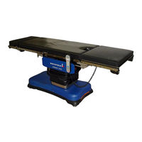
Berchtold OPERON B 810 Service Parts (120 pages)
Brand:
Berchtold
| Category:
Medical Equipment
| Size: 19 MB
Table of Contents
Table of Contents
3
Special Safety Instructions
11
Safety Symbols
11
Use Conditions
11
Power Supply
11
Pinch Points
11
Load Capacity
12
Figure S-1 Maximum Weight Location
12
Patient Positioning
13
Patient Orientation
13
Operation
13
Primary Hand Pendant Functions
13
Auxiliary Hand Pendant
13
Headrest
14
Removable Leg Section
14
Accessories Designed by Others
14
Radiolucent Table Top and Pads
14
Footswitch (Optional
14
Hydraulic System
14
Hollow Plugs
14
Hydraulic Fluid
14
Electromagnetic Interference
15
Electrical System
15
Service Program
15
Cleaning and Disinfection
16
Warning Labels
16
Figure S-2 Patient Safety Warning Label
16
Figure S-3 Fuse Label
16
General Information
17
General Description
17
Radiolucent Table Top and Pads
17
Interchangeable Headrest
17
Figure 1-1 Operon B 810 Surgical Table
17
Power Supply
18
Fuses
18
Figure 1-2 Base Components
18
Floor Lock System
19
Primary Hand Pendant
19
Figure 1-3 Product Identification and Fuse Information Label
19
Figure 1-4 Primary Hand Pendant and Footswitch Connector Box
19
Primary Hand Pendant Indicators
20
Figure 1-5 Primary Hand Pendant Indicators
20
Primary Hand Pendant Functions
21
Figure 1-6 Primary Hand Pendant Functions
21
Footswitch (Optional)
22
Manual Foot Pump
22
Figure 1-7 Footswitch
22
Figure 1-8 Deploying Foot Pump Pedal
22
Figure 1-9 Locking Foot Pump Pedal for Use
22
Auxiliary Hand Pendant
23
Figure 1-10 Auxiliary Hand Pendant
23
Operating Instructions
25
Pinch Points
25
Electromagnetic Interference
25
Load Capacity
25
Figure 2-1 Pinch Points
25
Patient Orientation
26
Normal Orientation
26
Reverse Orientation
26
Patient Positioning
26
Figure 2-2 Normal Table Orientation
26
Figure 2-3 Reverse Table Orientation
26
Operation
27
Figure 2-4 Normal Perineal Position
27
Figure 2-5 Reverse Perineal Position
27
Hand Pendant Operation
28
Figure 2-6 Hand Pendant Power-On Indicators
28
Function Priority
29
Software-Controlled Limits
29
Table 2-1. Software-Controlled Limits
30
User-Controlled Limits
31
Headrest
31
Figure 2-7 Headrest
31
Removable Leg Section
32
Footswitch (Optional)
32
Figure 2-8 Aligning the Leg Section for Installation
32
Figure 2-9 Leg Section
32
Figure 2-10 Assembled Leg Section
32
Figure 2-11 Footswitch
33
Backup Instructions
34
Figure 3-1 Backup Systems
34
Figure 3-2 Auxiliary Hand Pendant
34
Principles of Operation
35
Hydraulic System
35
Hydraulic Power Unit
35
Hydraulic Manifolds
35
Column Manifold
36
Floor Lock Manifolds
37
Floor Lock System Operation
38
Floor Lock Quick Disconnect
39
Manifold Valve Description
39
Manifold Valve Operation
40
Column Hydraulics
40
General Information
40
Figure 4-9. Column Cylinder Schematic
41
Table 4-2 Column Solenoids
41
Operation
42
Height up and down
42
Tilt Left and Right
42
Trendelenburg and Reverse Trendelenburg
42
Figure 4-10. Lift Tubes/Cylinders
42
Figure 4-11. Tilt Cylinder and Upper Lift Tube
42
Figure 4-12. Tilt Operation
42
Figure 4-13. Manifold and Solenoids
43
Figure 4-14. Hose Routing
43
Figure 4-15. Left Side Frame Cylinders
44
Figure 4-16. Right Side Frame Cylinders
44
Hollow Plugs and Seals
45
Using Hollow Plugs and Washers to Secure Hydraulic Lines
45
Hollow Plug Torque Specifications
46
Hydraulic Fluid
46
Table 4-3 Hollow Plug Torque Specifications
46
Electrical System
47
Cpu and Auxiliary Board
47
Connector Board
49
Table 4-4 Cpu Power Connectors
49
Table 4-5 Wiring Harness Applications
49
Extension Board
50
Position Sensors and Switches
50
Tilt and Trendelenburg Sensors
51
Slide Sensor
51
Kidney Switch
52
Auxiliary Pendant Switch
52
Power Supply System
53
Batteries
53
Battery Replacement
54
Power Input System
55
Left Power Center
55
Right Power Center
55
Table 4-6 Blade Fuses
55
Control Pendants
56
Primary Hand Pendant
56
Auxiliary Hand Pendant
57
Base Wiring
57
Base, Column, and Top Electrical Connections
58
Table 4-8 Base Electrical Connections Locations
58
Mechanical Slide System
61
Timing Belt Testing and Adjustment
63
Circuit Diagrams
64
Service Program
66
Introduction
72
Cpu Description
72
How to Use the Service Program
73
Connect to the Table
73
Launch the Service Program
73
The Hand Pendant Graphic
75
The Service Program Menus
75
File Menu
75
View Menu
76
Choose Cpu Menu
76
Load Data Menu
76
Free Access Menu
76
Open File Button
76
Save File Button
76
Copy to Button
76
Print System Settings Button
77
Com Button
78
Load Default Settings Button
78
Device Settings Button
78
Motor Tab
80
Valve Tab
81
Sensor Tab
81
ACCU Tab
84
Movements Tab
85
System Info Button
87
Cycle Test Button
89
Cpu Error Codes
91
Troubleshooting
96
Table 6-4. Troubleshooting Guide
97
Batteries and Charge Indicators
98
Introduction
98
Ac Detected
98
Ac Detected
99
Electrical Parameters
100
Supply Voltage
100
Periodic Maintenance
101
Electrical Inspection
101
Hydraulic System Operation
101
Ground Continuity/Leakage Current
101
Flexible Hydraulic Lines
101
Hydraulic Fluid Level
101
Fasteners and Retaining Clips
102
Clamps and Accessories
102
Structural Integrity of the Table
102
Cleaning and Disinfection
102
Stainless Steel Surfaces
102
Cleaning Methods
102
Cleaning Agents
102
Removing Stains
103
Applying Disinfectants
103
Painted Surfaces
103
Conductive Items
103
Hand Pendants
103
Parts
104
Introduction
105
Fastener Torque Requirements
105
Drawing Index
105
Table 8-1 General Fastener Torque Specifications
105
Advertisement
Berchtold OPERON B 810 Installation & Operating Manual (43 pages)
Brand:
Berchtold
| Category:
Medical Equipment
| Size: 2 MB
Table of Contents
Table of Contents
3
Special Safety Instructions
7
Pinch Points
7
Safety Symbols
7
Use Conditions
7
Control Pendants
8
Load Capacity
8
Figure S-1 Maximum Weight Location
9
Patient Positioning
9
Environmental Requirements
10
Operation
10
Unpacking
10
Accessories Designed by Others
11
Checks and Adjustment
11
Cleaning and Disinfection
11
Power Supply
11
Radiolucent Table Top and Pads
11
Warning Labels
12
Figure S-2 Patient Safety Warning Label
12
Figure S-3 Product Identification Label
12
Installation Instructions
13
Electrical Power Requirements
13
Environmental Requirements
13
Tools Required
13
Figure 1-1 Shipping Container
14
Unpacking
14
Figure 1-2 Shipping Clamps
15
Figure 1-4 Remove Table from Skid
16
Figure 1-5 Pad Set
16
Figure 1-6 Locking Levers
17
Figure 1-7 Headrest
17
Installing the Headrest
17
Ac Fuses (Mains Ac)
18
Figure 1-8 Chair Position
18
Setting the Table Levels
18
Figure 2-1 Operon B 810 Surgical Table
19
Fuses
20
Power Supply
20
Figure 1-3 Loading/Unloading Ramp
15
Checks and Adjustment
17
Installation
16
Installing the Pads
16
General Information
19
General Description
19
Interchangeable Headrest
19
Radiolucent Table Top and Pads
19
Figure 2-2 Base Components Power Supply
20
Figure 2-3 Product Identification and Fuse Information Label
21
Figure 2-4 Primary Hand pendant and Footswitch Connector Box
21
Figure 2-5 Hand pendant Power-On Indicators
22
Figure 2-6 Primary Hand pendant Indicators
23
Primary Hand pendant Functions
24
Primary Hand pendant Indicators
23
Floor Lock System
21
Primary Hand pendant
21
Hand pendant Operation
22
Figure 2-7 Primary Hand pendant Functions
24
Table of Contents
25
Figure 2-8 Footswitch
25
Figure 2-10 Locking the Foot Pump Pedal
25
Figure 2-9 Deploying the Foot Pump Pedal
25
Footswitch (Optional)
25
Manual Foot Pump
25
Auxiliary Hand pendant
26
Figure 2-11 Location of Auxiliary pendant and Drawer
26
Operating Instructions
27
Figure 2-12 Accessing the Auxiliary Hand pendant Keyboard
28
Figure 3-1 Pinch Points
28
Load Capacity
29
Patient Orientation
29
Normal Orientation
29
Reverse Orientation
29
Patient Positioning
29
Pinch Points
28
Figure 3-2 Normal Table Orientation
29
Figure 3-3 Reverse Table Orientation
29
Figure 3-4 Normal Perineal Position
30
Figure 3-5 Reverse Perineal Position
30
Figure 3-6 Headrest
33
Removable Leg Section
34
Function Priority
31
Software-Controlled Limits
31
User-Controlled Limits
33
Headrest
33
Operation
30
Figure 3-9 Assembled Leg Section
34
Figure 3-8 Leg Section
34
Figure 3-7 Aligning the Leg Section for Installation
34
Footswitch (Optional)
35
Figure 3-10 Footswitch
35
Backup Instructions
36
Figure 4-1. Backup Systems
36
Figure 4-2. Auxiliary Hand pendant
36
Maintenance
38
Periodic Maintenance
38
Cleaning and Disinfection
39
Stainless Steel Surfaces
39
Cleaning Methods
39
Cleaning Agents
39
Removing Stains
39
Applying Disinfectants
39
Painted Surfaces
39
Conductive Items
39
Hand Pendants
40
Important Telephone Numbers
40
Parts and Accessories
40
Advertisement
Related Products
Berchtold Operon D860
Berchtold Operon D850
Berchtold Operon D760
Berchtold Operon D830
Berchtold Operon D820
Berchtold Operon D770
Berchtold CHROMOPHARE E 558
Berchtold CHROMOPHARE E 668
Berchtold CHROMOPHARE E 778
Berchtold ELEKTROTOM 530
Berchtold Categories
Medical Equipment
Lighting Equipment
Personal Care Products
More Berchtold Manuals
Login
Sign In
OR
Sign in with Facebook
Sign in with Google
Upload manual
Upload from disk
Upload from URL