
Related Manuals for Parker EAPF 1


Summary of Contents for Parker EAPF 1
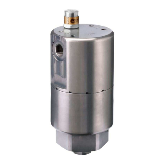
- Page 1 Parker Hannifin Manufacturing Netherlands (Filtration) B.V. EAPF 1 Ecological ATEX Pressure Filter -OPERATION AND MAINTENANCE INSTRUCTIONS- -SPARE PARTS- 72.09.195.66 rev.B EC-1520650...
-
Page 2: Table Of Contents
9.3. Changing vent plug ..........................17 9.4. Changing drain plug ..........................18 9.5. Venting filter housing ..........................19 10. SPARE PARTS ......................21 11. MANUFACTURER’S CONTACT INFORMATION ............24 APPENDIX A – EPF ELEMENT INSTRUCTION SHEET ..........25 © Parker Hannifin Manufacturing Netherlands (Filtration) B.V. -
Page 3: Preface
These operating and maintenance instructions shall be complemented with relevant instructions set forth in local acts and statutes, and in requirements by local authorities. © Parker Hannifin Manufacturing Netherlands (Filtration) B.V. -
Page 4: To The User
The manufacturer reserves the right to change the device or its operation and maintenance instructions without prior notice. • This operation and maintenance manual may not be copied, displayed in public, or given to a third party. © Parker Hannifin Manufacturing Netherlands (Filtration) B.V. -
Page 5: Safety Instructions
Incorrect use or maintenance of the device may cause danger to environment or the device itself READ OPERATION AND MAINTENANCE INSTRUCTIONS Prior to operating the device you shall read and fully understand the operation and maintenance instructions. © Parker Hannifin Manufacturing Netherlands (Filtration) B.V. -
Page 6: Operator Safety Instructions
Danger of slipping. Keep the maintenance area clean of oils or other substances that may cause slipping. Poisoning or allergy risk. None of the fluids used in the device may be swallowed. Avoid skin contact with fluid. © Parker Hannifin Manufacturing Netherlands (Filtration) B.V. -
Page 7: Technical Specifications
98 mm. x 312 mm. Filtering grade: For product setting see product code on nameplate Inlet / Outlet: For product setting see product code on nameplate Drain port: M26x1,5 Vent port: M16x1,5 Indicator port: ¾-16 UNF-2A © Parker Hannifin Manufacturing Netherlands (Filtration) B.V. -
Page 8: Main Components
8(26) Hydraulic Oil Filter EAPF 1 Operation and Maintenance Instructions 72.09.195.66 rev.B 5. MAIN COMPONENTS Indicator port Vent plug assembly Filter head O-ring Back-up ring O-ring Element Filter bowl Drain plug assembly © Parker Hannifin Manufacturing Netherlands (Filtration) B.V. -
Page 9: Description Of Operation
Oil enters the filter through the inlet connection by means of the machine system pressure. Oil is then flowing from the outside through the filter element, which captures contaminants. The filtered oil exits the filter through the outlet connection. © Parker Hannifin Manufacturing Netherlands (Filtration) B.V. -
Page 10: Installing And Commissioning
• All screws and connections are properly tightened according to manufacturer’s specifications. • If filtered fluid has high viscosity, provide the filter with thermal insulation and use extraheating for the fluid as necessary (consult manufacturer). © Parker Hannifin Manufacturing Netherlands (Filtration) B.V. -
Page 11: Installation Drawing / Torque Values
Hydraulic Oil Filter 11(26) EAPF 1 Operation and Maintenance Instructions 72.09.195.66 rev.B 7.3. Installation drawing / Torque values Indicator Hex: 24 mm Torque: 75 Nm Hex: 75 mm 50 mm © Parker Hannifin Manufacturing Netherlands (Filtration) B.V. -
Page 12: Use Of System
Before using the filter, make sure the bowl and all connections are fastened correctly. 8.2. General use of the filter Do not exceed specified pressure and flow limits. Check the differential pressure over the filter at regular intervals. © Parker Hannifin Manufacturing Netherlands (Filtration) B.V. -
Page 13: Malfunctions
> Make sure the oil cleanliness is correct. ———— >Replace the filter element, using an element with the correct filtering grade and according to the maintenance instructions. See maintenance instructions in chapter 9. © Parker Hannifin Manufacturing Netherlands (Filtration) B.V. -
Page 14: Maintenance Of The System
• Before any connections are opened, the system must be relieved of pressure. • Clean all connections and components in conjunction with maintenance work. • Check all connections for tightness. © Parker Hannifin Manufacturing Netherlands (Filtration) B.V. -
Page 15: Replacing The Filter Element
9.1. Replacing the filter element Before opening the filtration chamber make sure of the system is switched off and safe. Filter elements have to be replaced by using original Parker Hannifin filter elements. 1. Make sure the system is safe. 2. Drain the filter. -
Page 16: Installing Or Changing The Indicator
4. Install the indicator and tighten according instructions supplied with the indicator or plug. 5. If an electrical or electronic indicator used, make electric connections according instructions provided with indicator. 6. Vent the filter housing, see chapter © Parker Hannifin Manufacturing Netherlands (Filtration) B.V. -
Page 17: Changing Vent Plug
4. Place the plug/collar assembly into the nut. 5. Screw the plug into the housing. Making sure to use the torque values as shown in chapter 7.3. 6. Vent the filter housing, see chapter 9.5 © Parker Hannifin Manufacturing Netherlands (Filtration) B.V. -
Page 18: Changing Drain Plug
4. Place the plug/collar assembly into the nut. 5. Screw the plug into the housing. Making sure to use the torque values as shown in chapter 7.3. 6. Vent the filter housing, see chapter 9.5 © Parker Hannifin Manufacturing Netherlands (Filtration) B.V. -
Page 19: Venting Filter Housing
5. Wait until all the air is escaped and there is only system oil coming from the vent. 6. Tighten the vent plug. Making sure to use the torque values as shown in chapter 7.3. © Parker Hannifin Manufacturing Netherlands (Filtration) B.V. - Page 20 20(26) Hydraulic Oil Filter EAPF 1 Operation and Maintenance Instructions 72.09.195.66 rev.B SPARE PARTS & OPTIONAL ACCESSORIES © Parker Hannifin Manufacturing Netherlands (Filtration) B.V.
-
Page 21: Spare Parts
Hydraulic Oil Filter 21(26) EAPF 1 Operation and Maintenance Instructions 72.09.195.66 rev.B 10. SPARE PARTS © Parker Hannifin Manufacturing Netherlands (Filtration) B.V. - Page 22 Back-up ring Ø65/70 x 1.3 EAPFSK001 (NBR) / EAPFSK002 (Viton) O-ring Ø88,57 x 2,62 70SH EAPFSK001 (NBR) / EAPFSK002 (Viton) Bowl Filter element See table on the next page Drain plug M26 autoclave © Parker Hannifin Manufacturing Netherlands (Filtration) B.V.
- Page 23 On request Electronic 4 LED, NPN, NC On request Table 2 INDICATING PRESSURE Indicating pressure options CODE 2.5 bar 3.5 bar 5.0 bar Please note; the bold options reflect standard options with reduced lead-time. © Parker Hannifin Manufacturing Netherlands (Filtration) B.V.
-
Page 24: Manufacturer's Contact Information
Operation and Maintenance Instructions 72.09.195.66 rev.B 11. MANUFACTURER’S CONTACT INFORMATION Parker Hannifin Manufacturing Netherlands (Filtration) B.V. Mail address Stieltjesweg 8 6827 BV Arnhem The Netherlands Telephone +31 26 376 0376 +31 26 364 3620 www.parker.com © Parker Hannifin Manufacturing Netherlands (Filtration) B.V. -
Page 25: Appendix A - Epf Element Instruction Sheet
Hydraulic Oil Filter 25(26) EAPF 1 Operation and Maintenance Instructions 72.09.195.66 rev.B Appendix A – EPF element instruction sheet © Parker Hannifin Manufacturing Netherlands (Filtration) B.V.
Need help?
Do you have a question about the EAPF 1 and is the answer not in the manual?
Questions and answers