
Related Manuals for IBASE Technology BISD3-QM77


Summary of Contents for IBASE Technology BISD3-QM77
- Page 1 BISD3-QM77 ® Intel Gen. 2 Core i3/i5 based Mini ITX Motherboard User’s Manual Version 1.0 (Nov. 2016)
- Page 2 IBASE Technology, Inc. (hereinafter referred to as “IBASE”). Disclaimer IBASE reserves the right to make changes and improvements to the products described in this document without prior notice.
-
Page 3: Compliance
0.1% by weight (1000 ppm) except for cadmium, limited to 0.01% by weight (100 ppm). • Lead (Pb) • Mercury (Hg) • Cadmium (Cd) • Hexavalent chromium (Cr6+) • Polybrominated biphenyls (PBB) • Polybrominated diphenyl ether (PBDE) BISD3-QM77 User’s Manual... -
Page 4: Important Safety Information
Danger of explosion if the internal lithium-ion battery is replaced by an incorrect type. Replace only with the same or equivalent type recommended by the manufacturer. Dispose of used batteries according to the manufacturer’s instructions or recycle them at a local recycling facility or battery collection point. BISD3-QM77 User’s Manual... -
Page 5: Warranty Policy
Software in use (such as OS and application software, including the version numbers) If repair service is required, you can download the RMA form at http://www.ibase.com.tw/english/Supports/RMAService/. Fill out the form and contact your distributor or sales representative. BISD3-QM77 User’s Manual... -
Page 6: Table Of Contents
VGA & DVI-D Ports (CN2) ........... 22 2.5.3 USB 3.0 Port (CN3, CN5, CN7) ........... 22 2.5.4 HDMI Port (CN4) ..............22 2.5.5 LAN Port & USB 2.0 Ports (CN6, CN11) ......23 2.5.6 HD Audio Jacks (CN12) ............23 BISD3-QM77 User’s Manual... - Page 7 4.4.4 SATA Configuration ............. 53 4.4.5 Shutdown Temperature Configuration ........54 4.4.6 USB Configuration ............... 55 4.4.7 Super IO Configuration ............56 4.4.8 Hardware Monitor ..............58 4.4.9 CPU PPM Configuration ............59 Chipset Settings ................60 BISD3-QM77 User’s Manual...
- Page 8 System Agent (SA) Configuration ......... 63 Boot Settings ..................65 Security Settings ................66 Save & Exit Settings ................67 Appendix ..................68 I/O Port Address Map ................ 69 Interrupt Request Lines (IRQ) ............73 Watchdog Timer Configuration ............75 BISD3-QM77 User’s Manual viii...
-
Page 9: Chapter 1 General Information
Chapter 1 General Information The information provided in this chapter includes: Features Packing List Optional Accessories Block Diagram Specifications Board Overview Board Dimensions... -
Page 10: Introduction
Introduction ® BISD3-QM77 is a Mini ITX single board computer based on the platform of Intel Gen. 2 Core i3-2330M / i5-2520M. This board offers extensive I/O support, flexible display port connection and iAMT management. It is able to be operated at the ambient operating temperature ranging from 0 ~ 60 °C, and even from -20 ~ 80... -
Page 11: Packing List
General Information Packing List Your BISD3-QM77 package should include the items listed below. If any of the items below is missing, contact the distributor or dealer from whom you purchased the product. BISD3-QM77 SBC SATA Cable Disk (including drivers) ... -
Page 12: Specifications
12 ~ 24V DC-In (via ATX Power Connector) Watchdog Yes (256 segments, 0, 1, 2…255 sec / min) Timer H/W Monitor BIOS AMI BIOS iAMT 170 x 170 mm (6.7” x 6.7”) Dimensions RoHS Certification CE, FCC Class B (Pre-Scan) BISD3-QM77 User’s Manual... - Page 13 Operation: 0 ~ 60 °C (32 ~ 140 °F) Temperature Storage: -20 ~ 80 °C (-4 ~ 176 °F) Relative 10 ~ 90 %, non-condensing at 60 °C Humidity All specifications are subject to change without prior notice. BISD3-QM77 User’s Manual...
-
Page 14: Block Diagram
Block Diagram (rPGA988B socket) BISD3-QM77 User’s Manual... -
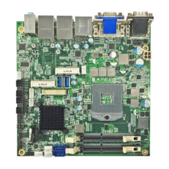
Page 15: Overview
General Information Overview Top View Bottom View *The photos above are for reference only. Some minor components may differ. BISD3-QM77 User’s Manual... - Page 16 I/O View Name Name COM1 RS-232/422/485 Port LAN Port COM2 RS-232/422/485 Port USB 2.0 Port VGA Port Line-In DVI-D Port Line-Out USB 3.0 Port Microphone Input HDMI Port BISD3-QM77 User’s Manual...
-
Page 17: Dimensions
General Information Dimensions BISD3-QM77 User’s Manual... -
Page 18: Chapter 2 Hardware Configuration
Hardware Configuration This section provides information on jumper settings and connectors on the BISD3-QM77 in order to set up a workable system. On top of that, you will also need to install crucial pieces such as the CPU and the memory before using the product. The topics covered are: ... -
Page 19: Essential Installations Before You Begin
Follow the instructions below to install the memory. 2.1.1 Installing the Memory The BISD3-QM77 board supports two DDR3/L memory socket for a maximum total memory of 16 GB. To install the modules, locate the memory slot on the board and perform the following steps: Hold the module so that the key of the module aligned with that on the memory slot. -
Page 20: Setting The Jumpers
Setting the Jumpers Set up and configure your BISD3-QM77 by using jumpers for various settings and features according to your needs and applications. Contact your supplier if you have doubts about the best configuration for your use. 2.2.1 How to Set Jumpers Jumpers are short-length conductors consisting of several metal pins with a non-conductive base mounted on the circuit board. -
Page 21: Jumper & Connector Locations
Hardware Configuration Jumper & Connector Locations Board diagram of BISD3-QM77 BISD3-QM77 User’s Manual... -
Page 22: Jumpers Quick Reference
Jumper Name Page CMOS Data Clearance ME Register Clearance AT / ATX Mode Selection COM1 RS-232/422/485 Power Selection COM2 RS-232/422/485 Power Selection Brightness Selection 2.4.1 CMOS Data Clearance (J12) Function Pin closed Illustration Normal (default) Clear CMOS BISD3-QM77 User’s Manual... -
Page 23: Me Register Clearance (J15)
Hardware Configuration 2.4.2 ME Register Clearance (J15) Function Pin closed Illustration Normal (default) Clear ME BISD3-QM77 User’s Manual... -
Page 24: At / Atx Mode Selection (Jp7)
2.4.3 AT / ATX Mode Selection (JP7) Function Pin closed Illustration (default) BISD3-QM77 User’s Manual... -
Page 25: Com1 Rs-232/422/485 Power Selection (Jp1)
Hardware Configuration 2.4.4 COM1 RS-232/422/485 Power Selection (JP1) Function Pin closed Illustration (default) BISD3-QM77 User’s Manual... -
Page 26: Com2 Rs-232/422/485 Power Selection (Jp2)
2.4.5 COM2 RS-232/422/485 Power Selection (JP2) Function Pin closed Illustration (default) BISD3-QM77 User’s Manual... -
Page 27: Brightness Selection (Jp3)
Hardware Configuration 2.4.6 Brightness Selection (JP3) Function Pin closed Illustration 3.3V Open (default) Close BISD3-QM77 User’s Manual... -
Page 28: Connectors Quick Reference
COM3 & COM4 RS-232 Connectors J10, J11 Front Panel Function Connector Digital I/O Connector LCD Backlight Connector JP4, JP5 Amplifier Output Connector CPU Fan Power Connector CPU_FAN1 System Fan Power Connector SYS_FAN1 Factory Use Only J8, JP6, JP8 BISD3-QM77 User’s Manual... -
Page 29: Com1 & Com2 Rs-232/422/485 Port (Cn1)
DCD, Data carrier detect DSR, Data set ready RXD, Receive data RTS, Request to send TXD, Transmit data CTS, Clear to send DTR, Data terminal ready RI, Ring indicator Ground Assignment RS-232 RS-422 RS-485 DATA- DATA+ Ground Ground Ground BISD3-QM77 User’s Manual... -
Page 30: Vga & Dvi-D Ports (Cn2)
2.5.2 VGA & DVI-D Ports (CN2) 2.5.3 USB 3.0 Port (CN3, CN5, CN7) 2.5.4 HDMI Port (CN4) BISD3-QM77 User’s Manual... -
Page 31: Lan Port & Usb 2.0 Ports (Cn6, Cn11)
Hardware Configuration 2.5.5 LAN Port & USB 2.0 Ports (CN6, CN11) 2.5.6 HD Audio Jacks (CN12) 2.5.7 SATA III Port (CN8, CN9) BISD3-QM77 User’s Manual... -
Page 32: Lvds Connectors (Cn10)
LVDSB_DATA1 LVDSB_DATA0 3.3V LVDSB_DATA1# LVDSB_DATA0# LVDS_DDC_CLK Ground LVDS_DDC_DATA Ground Ground LVDSB_DATA3 Ground LVDSB_DATA2 LVDSA_DATA1 LVDSB_DATA3# LVDSA_DATA0 LVDSB_DATA2# LVDSA_DATA1# Ground LVDSA_DATA0# Ground Ground LVDSB_CLK Ground LVDSA_CLK LVDSA_DATA3 LVDSB_CLK# LVDSA_DATA2 LVDSA_CLK# LVDSA_DATA3# Ground LVDSA_DATA2# Ground Ground BLON Ground BLON BISD3-QM77 User’s Manual... -
Page 33: Dc Power Input Connector (J1)
Hardware Configuration 2.5.9 DC Power Input Connector (J1) J1 connector supplies the CPU operating voltage. Assigment Assigment Ground Ground 2.5.10 DDR3 SO-DIMM Socket (J2, J3) BISD3-QM77 User’s Manual... -
Page 34: Half-Size Mini-Pcie (X1) Slot (J4)
2.5.11 Half-Size Mini-PCIe (x1) Slot (J4) 2.5.12 Full-Size Mini-PCIe (x1) / mSATA Slot (J7) BISD3-QM77 User’s Manual... -
Page 35: Hdd Power Connector (J5, J6)
Hardware Configuration 2.5.13 HDD Power Connector (J5, J6) Assigment Assigment Ground Ground 2.5.14 Front Panel Audio Control Connector (J9) Assigment Assigment MIC IN_L Ground Ground Sense MIC IN_R LINE_L LINE_R Ground BISD3-QM77 User’s Manual... -
Page 36: Com3 & Com4 Rs-232 Connector (J10, J11)
COM3 & COM4 RS-232 Connector (J10, J11) Assigment Assigment DCD# DSR# RTS# SOUT CTS# DTR# Ground 2.5.16 Front Panel Function Connector (J13) Assigment Assigment Power BTN Reset BTN Power BTN Reset BTN HDD LED+ Power LED+ HDD LED- Power LED- BISD3-QM77 User’s Manual... -
Page 37: Digital I/O (J14)
Power LED: Pins 7 and 8 This connector connects to the system power LED on control panel. This LED will light when the system turns on. 2.5.17 Digital I/O (J14) Assigment Assigment Ground Out0 Out3 Out1 Out2 BISD3-QM77 User’s Manual... -
Page 38: Lcd Backlight Connector (Jp4, Jp5)
2.5.18 LCD Backlight Connector (JP4, JP5) JP4: Assigment Assigment Ground LVDS BLON JP5: Assigment Assigment BLON LVDS BLON Ground BISD3-QM77 User’s Manual... -
Page 39: Amplifier Output Connector (Jp9)
Hardware Configuration 2.5.19 Amplifier Output Connector (JP9) Assigment Assigment SPK_R+ SPK_L- SPK_R- SPK_L+ 2.5.20 CPU Fan Power Connector (CPU_FAN1) Assigment Assigment Ground Rotation detection Control BISD3-QM77 User’s Manual... -
Page 40: System Fan Power Connector (Sys_Fan1)
2.5.21 System Fan Power Connector (SYS_FAN1) Assigment Assigment Ground Rotation detection Control BISD3-QM77 User’s Manual... -
Page 41: Chapter 3 Drivers Installation
Chapter 3 Drivers Installation This chapter introduces installation of the following drivers: ® Intel Chipset Software Installation Utility VGA Driver HD Audio Driver LAN Driver ® Intel Management Engine Interface ® Intel USB 3.0 Driver... -
Page 42: Introduction
The contents of this section include the following: Note: After installing your Windows operating system, you must install first the ® Intel Chipset Software Installation Utility before proceeding with the drivers installation. BISD3-QM77 User’s Manual... -
Page 43: Intel ® Chipset Software Installation Utility
Insert the disk enclosed in the package with the board. Click Intel and then Intel(R) 7 Series Chipset Drivers. Click Intel(R) Chipset Software Installation Utility. ® When the Welcome screen to the Intel Chipset Device Software appears, click Next to continue. BISD3-QM77 User’s Manual... - Page 44 Click Yes to accept the software license agreement and proceed with the installation process. On the Readme File Information screen, click Install for installation. The driver has been completely installed. Click Finish to restart the computer and for changes to take effect. BISD3-QM77 User’s Manual...
-
Page 45: Vga Driver Installation
Driver Installation VGA Driver Installation Insert the disk enclosed in the package with the board. Click Intel and then Intel(R) 7 Series Chipset Drivers. Click Intel(R) Core(TM) i3/i5/i7 Graphics Driver. BISD3-QM77 User’s Manual... - Page 46 Click Yes to agree with the license agreement and continue the installation. On the Readme File Information and Setup Progress screens, click Next for installation. The driver has been completely installed. Click Finish to restart the computer and for changes to take effect. BISD3-QM77 User’s Manual...
-
Page 47: Hd Audio Driver Installation
Driver Installation HD Audio Driver Installation Insert the disk enclosed in the package with the board. Click Intel and then Intel(R) 7 Series Chipset Drivers. Click Realtek High Definition Audio Driver. BISD3-QM77 User’s Manual... - Page 48 On the Welcome screen of the InstallShield Wizard, click Next for installation. The installation is complete. Click Finish to restart the computer and for changes to take effect. BISD3-QM77 User’s Manual...
-
Page 49: Lan Driver Installation
Driver Installation LAN Driver Installation Insert the disk enclosed in the package with the board. Click Intel and then Intel(R) 7 Series Chipset Drivers. Click Intel(R) PRO LAN Network Drivers. BISD3-QM77 User’s Manual... - Page 50 On the Setup Options screen, click the checkbox to select the desired driver(s) for installation. Then click Next to continue. The wizard is ready for installation. Click Install. As the installation is complete, click Finish and restart the computer and for changes to take effect. BISD3-QM77 User’s Manual...
-
Page 51: Intel ® Iamt 8.0 Driver Installation
Driver Installation ® Intel iAMT 8.0 Driver Installation Insert the disk enclosed in the package with the board. Click Intel and then Intel(R) 7 Series Chipset Drivers. Click Intel(R) iAMT 8.0 Drivers. BISD3-QM77 User’s Manual... - Page 52 Click Yes to agree with the license agreement and continue the installation. On the Readme File Information and Setup Progress screens, click Next for installation. The driver has been completely installed. Click Finish to restart the computer and for changes to take effect. BISD3-QM77 User’s Manual...
-
Page 53: Chapter 4 Bios Setup
Chapter 4 BIOS Setup This chapter describes the different settings available in the AMI BIOS that comes with the board. The topics covered in this chapter are as follows: Main Settings Advanced Settings Chipset Settings Boot Settings ... -
Page 54: Introduction
The following message will appear on the screen: Press <DEL> Enter Setup In general, press the arrow keys to highlight items, <Enter> to select, the <PgUp> and <PgDn> keys to change entries, <F1> for help, and <Esc> to quit. BISD3-QM77 User’s Manual... - Page 55 Warning: It is strongly recommended that you avoid making any changes to the chipset defaults. These defaults have been carefully chosen by both AMI and your system manufacturer to provide the absolute maximum performance and reliability. Changing the defaults could make the system unstable and crash in some cases. BISD3-QM77 User’s Manual...
-
Page 56: 4.3 Main Settings
4.3 Main Settings BIOS Setting Description System Date Sets the date. Use the <Tab> key to switch between the data elements. System Time Set the time. Use the <Tab> key to switch between the data elements. BISD3-QM77 User’s Manual... -
Page 57: 4.4 Advanced Settings
BIOS Setup 4.4 Advanced Settings This section allows you to configure, improve your system and allows you to set up some system features according to your preference. BISD3-QM77 User’s Manual... -
Page 58: Acpi Computing
Enables / Disables the system ability to hibernate (OS/S4 Sleep State). This option may be not effective with some OS. ACPI Sleep State Selects an ACPI sleep state where the system will enter when the Suspend button is pressed. BISD3-QM77 User’s Manual... -
Page 59: Wake Up Event Setting
Wake on Ring Enables / Disables the device to wake up and resume from a suspend state on alarm events. Wake on PCI PME Enables / Disables the device to wake up and resume from a suspend state. BISD3-QM77 User’s Manual... -
Page 60: Cpu Configuration
OS (Windows Server 2003 SP1, Windows XP SP2, SuSE Linux 9.2, RedHat Enterprise 3 Update 3.) Intel Virtualization When enabled, a VMM can utilize the additional Technology hardware capabilities provided by Vanderpool Technology. BISD3-QM77 User’s Manual... -
Page 61: Sata Configuration
SATA Controller Selects the SATA controller speed as Default / Speed Gen1 / Gen2 / Gen3. Serial ATA Port 0~5 Enables / Disables Serial Port 0~5. SATA Port 0~5 Enables / Disables SATA Port 0~5 HotPlug. HotPlug BISD3-QM77 User’s Manual... -
Page 62: Shutdown Temperature Configuration
4.4.5 Shutdown Temperature Configuration BISD3-QM77 User’s Manual... -
Page 63: Usb Configuration
The maximum time the device will take before it delay properly reports itself to the Host Controller. “Auto” uses default value for a Root port it is 100ms. But for a Hub port, the delay is taken from Hub descriptor. BISD3-QM77 User’s Manual... -
Page 64: Super Io Configuration
4.4.7 Super IO Configuration BIOS Setting Description Serial Ports Sets parameters of Serial Ports. Configuration Enables / Disables the serial port and select an optimal setting for the Super IO device. BISD3-QM77 User’s Manual... - Page 65 BIOS Setup 4.4.7.1. Serial Port 0 Configuration BIOS Setting Description Change Settings Selects an optimal settings for the Super I/O device. Device Mode Changes the mode of serial port. BISD3-QM77 User’s Manual...
-
Page 66: Hardware Monitor
Enables / Disables the smart fan feature. Temperatures / These fields are the parameters of the hardware Voltages monitoring function feature of the motherboard. The values are read-only values as monitored by the system and show the PC health status. BISD3-QM77 User’s Manual... -
Page 67: Cpu Ppm Configuration
BIOS Setup 4.4.9 CPU PPM Configuration BIOS Setting Description EIST Enables / Disables Intel SpeedStep. BISD3-QM77 User’s Manual... -
Page 68: 4.5 Chipset Settings
4.5 Chipset Settings BIOS Setting Description PCH-IO Configuration PCH parameters System Agent (SA) System Agent (SA) parameters Configuration BISD3-QM77 User’s Manual... -
Page 69: Pch-Io Configuration
BIOS Setup 4.5.1 PCH-IO Configuration 4.5.1.1. USB Configuration BIOS Setting Description XHCI Pre-Boot Driver Enables / Disables XHCI pre-boot driver support. BISD3-QM77 User’s Manual... - Page 70 4.5.1.2. PCH Azalia Configuration BIOS Setting Description Azalia Enables / Disables detection of the Azalia device unconditionally. “Auto” keeps Azalia to the present status as being enabled or disabled. BISD3-QM77 User’s Manual...
-
Page 71: System Agent (Sa) Configuration
BIOS Setup 4.5.2 System Agent (SA) Configuration BIOS Setting Description VT-d Checks if VT-d function on MCH is supported. BISD3-QM77 User’s Manual... - Page 72 4.5.2.1. Graphics Configuration BIOS Setting Description Primary Display Selects which of IGFX/PEG/PCI graphics device should be primary display, or selects SG for switchable Gfx. Internal Graphics Keeps IGD enabled based on the setup options. 4.5.2.2. Memory Configuration BISD3-QM77 User’s Manual...
-
Page 73: 4.6 Boot Settings
RT code is executed above 1 Option ROM Sets a display mode, Force BIOS or Keep Messages Current, for Option ROM. Interrupt 19 Capture Allows Option ROMs to trap Interrupt 19. Boot Option Priorities Sets the system boot order. BISD3-QM77 User’s Manual... -
Page 74: 4.7 Security Settings
4.7 Security Settings BIOS Setting Description Administrator Sets an administrator password for the setup Password utility. User Password Sets a user password. BISD3-QM77 User’s Manual... -
Page 75: 4.8 Save & Exit Settings
Restore Defaults Restores / Loads defaults values for all the setup options. Save as User Defaults Saves the changes done so far as User Defaults. Restore User Defaults Restores the user defaults to all the setup options. BISD3-QM77 User’s Manual... -
Page 76: Appendix
Appendix This section provides the mapping addresses of peripheral devices and the sample code of watchdog timer configuration. -
Page 77: I/O Port Address Map
Motherboard resources 0x00000200-0x0000020F Motherboard resources 0x0000FFFF-0x0000FFFF Motherboard resources 0x0000FFFF-0x0000FFFF Motherboard resources 0x00000400-0x00000453 Motherboard resources 0x00000458-0x0000047F Motherboard resources 0x00000500-0x0000057F Motherboard resources 0x0000164E-0x0000164F Motherboard resources 0x0000F040-0x0000F05F Intel(R) 7 Series/C216 Chipset Family SMBus Host Controller - 1E22 0x000000F0-0x000000FF Numeric data processor BISD3-QM77 User’s Manual... - Page 78 Communications Port (COM1) 0x000002F8-0x000002FF Communications Port (COM2) 0x000003E8-0x000003EF Communications Port (COM3) 0x000002E8-0x000002EF Communications Port (COM4) 0x00000454-0x00000457 Motherboard resources 0x00000000-0x00000CF7 PCI Express Root Complex 0x00000000-0x00000CF7 Direct memory access controller 0x00000D00-0x0000FFFF PCI Express Root Complex 0x00000081-0x00000091 Direct memory access controller BISD3-QM77 User’s Manual...
- Page 79 Motherboard resources 0x00000020-0x00000021 Programmable interrupt controller 0x00000024-0x00000025 Programmable interrupt controller 0x00000028-0x00000029 Programmable interrupt controller 0x0000002C-0x0000002D Programmable interrupt controller 0x00000030-0x00000031 Programmable interrupt controller 0x00000034-0x00000035 Programmable interrupt controller 0x00000038-0x00000039 Programmable interrupt controller 0x0000003C-0x0000003D Programmable interrupt controller 0x000000A0-0x000000A1 Programmable interrupt controller BISD3-QM77 User’s Manual...
- Page 80 Address Device Description 0x000000A4-0x000000A5 Programmable interrupt controller 0x000000A8-0x000000A9 Programmable interrupt controller 0x000000AC-0x000000AD Programmable interrupt controller 0x000000B0-0x000000B1 Programmable interrupt controller 0x000000B4-0x000000B5 Programmable interrupt controller 0x000000B8-0x000000B9 Programmable interrupt controller 0x000000BC-0x000000BD Programmable interrupt controller BISD3-QM77 User’s Manual...
-
Page 81: Interrupt Request Lines (Irq)
Intel(R) 7 Series/C216 Chipset Family USB Enhanced Host Controller - 1E26 IRQ 81 ~ 191 Microsoft ACPI-Compliant System IRQ 256 ~ 511 Microsoft ACPI-Compliant System IRQ 4294967289 Intel(R) USB 3.0 eXtensible Host Controller - 0100 (Microsoft) IRQ 4294967290 Intel(R) HD Graphics 3000 BISD3-QM77 User’s Manual... - Page 82 Intel(R) 7 Series/C216 Chipset Family PCI Express Root Port 6 - 1E1A IRQ 4294967293 Intel(R) 7 Series/C216 Chipset Family PCI Express Root Port 1 - 1E10 IRQ 4294967294 Xeon E3-1200/2nd Generation Intel(R) Core(TM) Processor Family PCI Express Root Port - 0101 BISD3-QM77 User’s Manual...
-
Page 83: Watchdog Timer Configuration
**endptr; char SIO; printf("Fintek 81866 watch dog program\n"); SIO = Init_F81866(); if (SIO == 0) printf("Can not detect Fintek 81866, program abort.\n"); return(1); }//if (SIO == 0) if (argc != 2) printf(" Parameter incorrect!!\n"); return (1); BISD3-QM77 User’s Manual... - Page 84 //--------------------------------------------------------------------------- void DisableWDT(void) unsigned char bBuf; Set_F81866_LD(0x07); //switch to logic device 7 bBuf = Get_F81866_Reg(0xFA); bBuf &= ~0x01; Set_F81866_Reg(0xFA, bBuf); //disable WDTO output bBuf = Get_F81866_Reg(0xF5); bBuf &= ~0x20; bBuf |= 0x40; Set_F81866_Reg(0xF5, bBuf); //disable WDT //--------------------------------------------------------------------------- BISD3-QM77 User’s Manual...
- Page 85 //Fintek 81866 goto Init_Finish; F81866_BASE = 0x00; result = F81866_BASE; Init_Finish: return (result); //--------------------------------------------------------------------------- void Unlock_F81866 (void) outportb(F81866_INDEX_PORT, F81866_UNLOCK); outportb(F81866_INDEX_PORT, F81866_UNLOCK); //--------------------------------------------------------------------------- void Lock_F81866 (void) outportb(F81866_INDEX_PORT, F81866_LOCK); //--------------------------------------------------------------------------- void Set_F81866_LD( unsigned char LD) Unlock_F81866(); outportb(F81866_INDEX_PORT, F81866_REG_LD); outportb(F81866_DATA_PORT, LD); BISD3-QM77 User’s Manual...
- Page 86 #define F81866_DATA_PORT (F81866_BASE+1) //--------------------------------------------------------------------------- #define F81866_REG_LD 0x07 //--------------------------------------------------------------------------- #define F81866_UNLOCK 0x87 #define F81866_LOCK 0xAA //--------------------------------------------------------------------------- unsigned int Init_F81866(void); void Set_F81866_LD( unsigned char); void Set_F81866_Reg( unsigned char, unsigned char); unsigned char Get_F81866_Reg( unsigned char); //--------------------------------------------------------------------------- #endif // F81866_H BISD3-QM77 User’s Manual...
Need help?
Do you have a question about the BISD3-QM77 and is the answer not in the manual?
Questions and answers