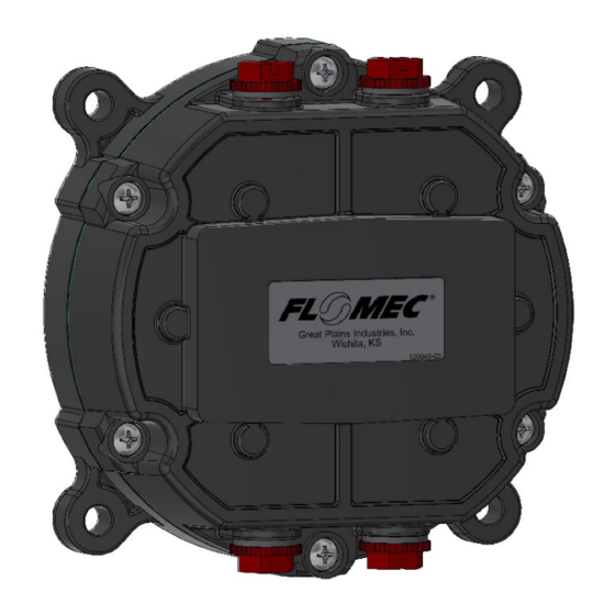
Flomec QSI1 Products Installation Instructions
Hide thumbs
Also See for QSI1:
- Installation instructions manual (21 pages) ,
- Owner's manual (16 pages) ,
- Installation instructions manual (8 pages)
Table of Contents
Advertisement
Quick Links
Advertisement
Table of Contents

Summary of Contents for Flomec QSI1
- Page 1 QSI ELECTRONIC MODULE For FLOMEC® Remote Applications 01/2022 920897-05 Rev. D...
- Page 2 This instruction covers the installation of the “no display” electronic module and the “display ready” electronic module with QSI1, QSI2, or QSI3 versions of communications electronics installed. The basic mechanical installation is the same for all electronic modules. The wiring connections and wiring diagrams differ depending on the electronic module being installed.
-
Page 3: Specifications
SPECIFICATIONS MECHANICAL ELECTRICAL Pollution Degree Female 1/2-20 UNF- Cover Plate 2B (Compatible with Installation Port Threads PG7 thread) Category Port Strain Altitude 2000m Max. Hubble PG7 Relief Indoor use only 0.11”-0.26” Grip Range OUTPUTS & COMMUNICATION (2.79 - 6.6mm) QSI Version 1: Port Conduit GPI PG7 x 1/2 in. - Page 4 SPECIFICATIONS (continued) DIMENSIONS Dimensions are shown in inches and [mm] Figure 1 APPROVALS & RATINGS RoHS Compliant (2011/65/EU) This product is in compliance with the RoHS Directive of the European Parliament and of the Council on the Restriction of the Use of Certain Hazardous Substances in Electrical and Electronic Equipment.
-
Page 5: Important Notice
INTRODUCTION The QSI communications module is a multiple capability electronics package and has three versions (QSI1, QSI2 or QSI3) available; each with its own mix of capabilities to better serve the customer (See Versions below). The module is also available as a “display ready” version with no display installed, but ready for the customer to install their own GPI “09”... - Page 6 ASSEMBLY INSTRUCTIONS NOTE: For DISPLAY READY QSI electronic modules only. For the “Display Ready” QSI module, follow these initial instructions first to install your customer provided display to the cover plate in the kit. Then follow the Installation Instructions to install this customer-assembled unit to the meter 1.
-
Page 7: Installation
INSTALLATION NOTE: For ALL QSI electronic modules. 1. Make sure the QSI module and meter are disconnected from power source. 2. Select the mounting location and mount the remote module using the (4) mounting ears on the base. The holes in the ears will accommodate a 1/4 in. diameter bolt or screw. - Page 8 INSTALLATION (continued) NOTE: The below figure is for all QSI electronic modules, even though the “display ready” version is not shown in the pictorial. STRAIN RELIEFS SHOWN INSTALLED Figure 2...
-
Page 9: Wiring Diagrams
WIRING DIAGRAMS TERMINAL CONNECTIONS CHART Figure 3 TEMP SENSOR Coil A Low level sine wave input PT100-Red Sensor VCC Output Coil B Low level sine wave input PT100-White Input High Side GPI SENSOR Ribbon cable connection to GPI custom PT100-Blue Input Return sensor designs PULSE OUTPUT... - Page 10 QSI1 WIRING QSI VERSION 1 – PC BOARD RS-485 Figure 4 QSI VERSION 1 - WIRING DIAGRAM Inputs: Temperature Sensors, Variable Reluctance, Pickup Coil Outputs: RS-485, Pulse Output Figure 5...
- Page 11 QSI2 WIRING QSI VERSION 2 – PC BOARD Pulse In Figure 6 QSI VERSION 2 - WIRING DIAGRAM Inputs: Temperature Sensors, Variable Reluctance, Pickup Coil Output: Pulse Output Figure 7...
- Page 12 QSI3 WIRING QSI VERSION 3 – PC BOARD 4-20mA Figure 8 QSI VERSION 3 - WIRING DIAGRAM Customer Equipment with Built-in Power Supply Inputs: Standard Remote Sensor (Variable Reluctance Pickup Coil) Outputs: Customer Equipment, 4-20mA Sensing, Built-in Loop Power Supply Minimum signal amplitude required for normal operation is approximately 15mV P-P.
- Page 13 QSI3 WIRING - (continued) QSI VERSION 3 - WIRING DIAGRAM Customer Equipment without Built-in Power Supply Inputs: Standard Remote Sensor (Variable Reluctance Pickup Coil) Outputs: 4-20mA with Separate Power Supply Note: Either of the wiring diagrams below (Low Side Negative Wiring-Figure 10A) or (High Side Positive Wiring-Figure 10B) are valid, as long as the current direction arrows and the (+) and (-) connections on all of the equipment in the loop are correct.
- Page 14 Open Collector Signal NOTE: Pull up resistor shown in FLOMEC Conditioned Signal Output Module wiring diagram above is not required for use with QSI Versions 1, 2, or 3. If the resistor is already installed, there is no need to remove it.
-
Page 15: Maintenance
MAINTENANCE Check cable-entry seals periodically. Tighten and/or apply sealant if needed. This is especially important in environments containing heavy concentrations of dust, oil mist, or other residue. Check all wiring connections occasionally for oxidation or corrosion. Clean and re- seat if such conditions are noted. If necessary, check and re-seat any connections that may have been subjected to strain (during rework or construction, for example). - Page 16 MAINTENANCE (continued) REPLACING BATTERY (continued) STRAIN RELIEFS NOT SHOWN Figure 12 Figure 13 Figure 14 Figure 15...
-
Page 17: Returning Parts
SERVICE For warranty consideration, contact your local distributor. If you need further assistance, contact the GPI Customer Service Department at: 1-888-996-3837 You will need to: • Provide information from the decal on your meter. • Receive a Return Authorization number. •... - Page 18 NOTES ________________________________________________________________ ________________________________________________________________ ________________________________________________________________ ________________________________________________________________ ________________________________________________________________ ________________________________________________________________ ________________________________________________________________ ________________________________________________________________ ________________________________________________________________ ________________________________________________________________ ________________________________________________________________ ________________________________________________________________ ________________________________________________________________ ________________________________________________________________ ________________________________________________________________ ________________________________________________________________ ________________________________________________________________ ________________________________________________________________ ________________________________________________________________ ________________________________________________________________ ________________________________________________________________ ________________________________________________________________ ________________________________________________________________ ________________________________________________________________ ________________________________________________________________ ________________________________________________________________ ________________________________________________________________...
- Page 19 NOTES ________________________________________________________________ ________________________________________________________________ ________________________________________________________________ ________________________________________________________________ ________________________________________________________________ ________________________________________________________________ ________________________________________________________________ ________________________________________________________________ ________________________________________________________________ ________________________________________________________________ ________________________________________________________________ ________________________________________________________________ ________________________________________________________________ ________________________________________________________________ ________________________________________________________________ ________________________________________________________________ ________________________________________________________________ ________________________________________________________________ ________________________________________________________________ ________________________________________________________________ ________________________________________________________________ ________________________________________________________________ ________________________________________________________________ ________________________________________________________________ ________________________________________________________________ ________________________________________________________________ ________________________________________________________________...
- Page 20 To make a claim against this warranty, or for technical assistance or repair, contact your FLOMEC distributor or contact FLOMEC at one of the locations below. In North or South America contact Outside North or South America contact Great Plains Industries, Inc.


Need help?
Do you have a question about the QSI1 and is the answer not in the manual?
Questions and answers