Flomec G2 Owner's Manual
Pulse access, external power & scaled pulse module
Hide thumbs
Also See for G2:
- Owner's manual (24 pages) ,
- Products installation instructions (21 pages)
Table of Contents
Advertisement
Quick Links
Advertisement
Table of Contents

Related Manuals for Flomec G2


Summary of Contents for Flomec G2
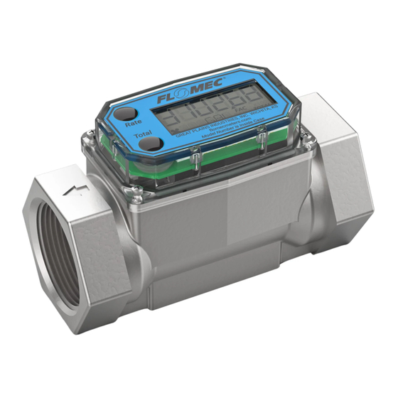
- Page 1 Module shown installed on G2 1” stainless steel flowmeter Module can be installed on all FLOMEC meters with Q9 display. Pulse Access, External Power & Scaled Pulse Module FOR USE WITH ALL TURBINE METERS WITH Q9 DISPLAY 09/2021 920909-01 Rev. C...
- Page 2 Please save these instructions for future reference. Read carefully before attempting to assemble, install, operate or maintain the product described. Protect yourself and others by observing all safety information. Failure to comply with instructions could result in personal injury and/or property damage. Please refer to back cover for information regarding this product’s warranty and other important information.
-
Page 3: Table Of Contents
TABLE OF CONTENTS Getting Started --------------------------------------------- 4 Electrical / Mechanical Specifications ---------------- 5 Approval Ratings ------------------------------------------ 7 Installation --------------------------------------------------- 8 Installing Module ------------------------------------- 8 Wiring --------------------------------------------------- 9 Operation / Calibration ---------------------------------- 12 Troubleshooting ------------------------------------------ 13 Pulse Output Flowchart --------------------------- 14 Parts List --------------------------------------------------- 15 Parts &... -
Page 4: Getting Started
BEFORE YOU BEGIN Usage Requirements This Pulse Access, External Power & Scaled Pulse module is not FM • Approved. Therefore, use of this module with an approved metering system voids FM Approval. This module is designed for use with all meters that are equipped with the •... -
Page 5: Electrical / Mechanical Specifications
Cable Length 10 ft. (3m), provided Operating 0° to +140°F (-18° to +60°C) Temperature When installed on G2 Stainless Steel Flowmeters, see Higher Process Fluid Ambient and Fluid Temperature Limits graph on next Temperatures page for higher process fluid temperature Limits. - Page 6 SPECIFICATIONS (continued) AMBIENT AND FLUID TEMPERATURE LIMITS NOTE: The upper limit of the “Useable Combination” area can be increased by 10°F (6°C) when lithium batteries are installed in the Q9 Display.
-
Page 7: Approval Ratings
SPECIFICATIONS (continued) DIMENSIONS Length Height Width Strain Relief 3.45 in. 0.90 in. 2.18 in. 0.77 in. (8.8 cm) (2.3 cm) (5.5 cm) (1.96 cm) Module shown installed on G2 1” stainless steel flowmeter Figure 1 APPROVAL RATINGS... -
Page 8: Installation
Once the cables are installed on the display, the housing of the display can be placed on top of the module (see Figure 2). Install the computer electronics to the front side of the turbine. Tighten the four screws snugly. Module shown installed on G2 1” stainless steel flowmeter Figure 2... -
Page 9: Wiring
INSTALLATION (continued) WIRING The Pulse Access module comes pre-wired for external connections to external power and provides an open collector output, which can be set for either raw or scaled pulse output. The wires are color-coded and are to be connected as shown in Figures 3 & 4. Wire Color Feature Black... - Page 10 INSTALLATION (continued) WIRING (continued) NOTE: The internal and external options for the pull up resistance and voltage is selectable by the header on the pulse access board (see Figures 4a & 4b). When the Jumper is on the top two pins, the “external resistor required” option is selected (Figure 4a).
- Page 11 INSTALLATION (continued) WIRING (continued) Wiring Example 1 Customer's Equipment: ● Built in Power ● Built in Pull-Up Resistor (via Customer’s Equipment) ● Use Scaled Pulse Output Module’s External Pull-up Resistor Jumper Setting (Fig 4a). Figure 5a Wiring Example 2 Customer's Equipment: ● No Built in Power ●...
-
Page 12: Operation / Calibration
OPERATION / CALIBRATION ADJUSTING SCALED PULSE K-FACTOR To set or adjust Scaled Pulse K-Factor settings, refer to the Q9 Owner’s Manual (Non- Agency) Field Calibration Section for further instructions (see below). You can download the Q9 Owner’s Manual (Non-Agency) here: or visit flomecmeters.com to download owner’s manuals and other technical documents. -
Page 13: Troubleshooting
TROUBLESHOOTING Symptom Possible Cause(s) Corrective Action A. No output signal. 1. Incorrect or no input power. 1. Supply correct power requirements. 2. Not wired correctly. 2. Check owner’s manual for correct installation. 3. Broken connection. 3. Check resistance to determine location of break. -
Page 14: Pulse Output Flowchart
TROUBLESHOOTING (continued) PULSE OUTPUT FLOWCHART... -
Page 15: Parts List
PARTS LIST Part No. Description 901002-52 Seal PARTS & SERVICE For warranty consideration, parts, or other service information, please contact your local distributor. If you need further assistance, contact the GPI Product Support Department in Wichita, Kansas, during normal business hours. A toll free number is provided for your convenience. -
Page 16: Warranty
To make a claim against this warranty, or for technical assistance or repair, contact your FLOMEC distributor or contact FLOMEC at one of the locations below. In North or South America contact Outside North or South America contact Great Plains Industries, Inc.
Need help?
Do you have a question about the G2 and is the answer not in the manual?
Questions and answers