Table of Contents
Advertisement
Quick Links
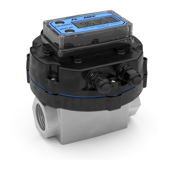
QSB & QSI Electronic Module for G2 Meters
Installation Instructions
These installation instructions cover
the installation of the following
electronic modules to G2 meters:
• QSB pulse output, with or without
a display.
• QSI1, QSI2, QSI3 versions of
communications electronics, with
or without a display.
10/2018
The basic mechanical installation is
the same for all electronic modules.
The wiring connections and wiring
diagrams differ depending on the
electronic module being installed.
920897-02 Rev C
Advertisement
Table of Contents

Related Manuals for Flomec QSB


Summary of Contents for Flomec QSB
- Page 1 QSB & QSI Electronic Module for G2 Meters Installation Instructions The basic mechanical installation is These installation instructions cover the same for all electronic modules. the installation of the following The wiring connections and wiring electronic modules to G2 meters: diagrams differ depending on the •...
- Page 2 MODULE CONTENTS Check the contents of your module using the list below as reference. • (1) Completely assembled QSB • (1) Gasket or QSI module (with or without a • (1) Instruction sheet. display). • (1) Q09 Owner’s manual (if module •...
- Page 3 Add .40 [10.1] per side 4.91 for strain relief projection [124.7] when installed in ports. 5.14 [130.6] 1.32 [33.5] 2.05 [52.0] 3.49 [88.7] 1.76 [44.6] G2-QSB OR QSI MODULE [18.0] WITH DISPLAY 4.91 [124.7] 5.14 [130.6] 1.32 2.05 [33.5] [52.0] 2.79 [70.8] 1.76 [44.6]...
-
Page 4: Important Notice
GPI or other sources of electronic noise. display. If the QSB or QSI electronics are QSB: used in a manner not specified by the manufacturer, the protection The QSB module is equipped with provided by the equipment may be pulse-out electronics. - Page 5 ASSEMBLY INSTRUCTIONS 4. Using a small regular screwdriver, NOTE: For Display Ready QSI remove the clear sealant from the Modules Only. 10 pin female connector holes on the backside of your display. For the “Display Ready” QSI module, follow these initial instructions first 5.
- Page 6 9. Mount the cover plate on the PVDF meters. base making sure the seal is seated properly between them. Replace the (6) previously removed screws to secure the cover plate to the base. Tighten screws. 10. Connect power to QSB or QSI module and meter.
- Page 7 The coil has a foam spacer combination in its recess on the adapter (see Figure 4). (6) SCREWS, #8-16 X 3/4 COVER PLATE (QSB OR QSI W/DISPLAY) (SHOWN) (QSB) (NO DISPLAY) (DISPLAY READY) (4) STRAIN RELIEF SEAL...
-
Page 8: Power Input
TERMINAL CONNECTIONS CHART PT100-Red PT100-White Sensor #1 PT100-Blue PT100-Red GPI Sensor PT100-White Sensor #2 PT100-Blue RS-485 + Coil A RS-485 - Coil B Pulse Output RS-485 GND RS-485 Pulse Input Power 4-20mA Figure 5 TEMP SENSOR Low level sine wave Coil A input PT100-Red... - Page 9 2500V galvanic isolation resistance must be chosen such from the QSB digital circuitry to that the QSB will not sink more than the external customer equipment. 30mA of current. The external power The QSB pulse output is an open...
-
Page 10: Wiring Diagram
WIRING DIAGRAMS WIRING DIAGRAM Output: Pulse Output ISOLATED PWR SUPPLY 12-30VAC, 50-60Hz / 12-36VDC Coil A & B (Non-polarized) Power (-) Power (+) Customer Pulse Out (+) Equipment Open Collector Unpowered Pulse Out (-) Pulse Input Pickup Coil Coil A Coil B Figure 7 The wire gauge for the pulse output... - Page 11 WIRING DIAGRAMS QSI VERSION 1 PC BOARD RS-485 RTDs RS-485 Pulse Out Power In Coil A & B (Non-polarized wires) Figure 8 WIRING DIAGRAM ISOLATED POWER SUPPLY Inputs: Temp Sensors, Variable Reluctance, Pickup Coil 12-30 V (ac) or Outputs: RS-485, Pulse Output 12-36 V (dc) QSI Version 1 Power (-)
- Page 12 WIRING DIAGRAMS QSI VERSION 2 PC BOARD Pulse In RTDs Coil A & B (Non-polarized wires) Pulse Out Power In Figure 10 WIRING DIAGRAM ISOLATED POWER SUPPLY Input: Temp Sensors, Variable Reluctance, Pickup Coil 12-30 V (ac) or Output: Pulse Output 12-36 V (dc) QSI Version 2 Power (-)
- Page 13 WIRING DIAGRAMS QSI VERSION 3 PC BOARD 4-20mA Coil A & B (Non-polarized wires) Pulse Out Power In 4-20mA Figure 12 WIRING DIAGRAM - 4-20mA and Pulse Outputs Customer Equipment with Built-in Power Supply Inputs: Standard Remote Sensor (Variable Reluctance Pickup Coil) Outputs: Customer Equipment, 4-20mA Sensing, Built-in Loop Power Supply Inputs Isolated Outputs...
- Page 14 mmended maximum cable length - 20ft. WIRING DIAGRAMS 4-20mA WIRING DIAGRAM Customer Equipment without Built-in Power Supply - 4-20mA Output with Separate Power Supply ISOLATED QSI Version 3 POWER SUPPLY 12-30 V (ac) or 12-36 V (dc) Customer Power (-) Equipment Power (+) 4-20mA (+)
-
Page 15: Power Supply
SPECIFICATIONS MECHANICAL Female 1/2-20 UNF-2B Cover Plate Port Threads (Compatible with PG7 thread) Port Strain Relief Hubble PG7 Grip Range 0.11”-0.26” (2.79 - 6.6mm) Operation Temperature +32°F to +140°F (0°C to +60°C) Ambient Air Operation Temp 0°F to +140°F (-18°C to +60°C) POWER SUPPLY Min. -
Page 16: With Display
FLOMEC APP FOR ANDROID To Replace Battery: To learn how to get started using the DISCONNECT POWER FLOMEC App, visit: TO METER FLOMEC.net/downloads/flomec- WITHOUT DISPLAY app-quickstart.pdf • Remove (6) screws retaining the cover plate to the base and lift the cover plate free of the base (see Figure 15). - Page 17 Figure 15 Figure 17 Figure 18 Figure 16 ...
-
Page 18: Returning Parts
SERVICE The Waste Electrical and Electronic Equipment (WEEE) directive For warranty consideration, contact (2002/96/EC) was approved by the your local distributor. If you need European Parliament and the Council further assistance, contact the GPI of the European Union in 2003. This symbol indicates that this product Customer Service Department at: contains electrical and electronic... - Page 19 NOTES...
- Page 20 Note: In compliance with MAGNUSON MOSS CONSUMER WARRANTY ACT – Part 702 (governs the resale availability of the warranty terms). © 2018 Great Plains Industries, Inc., All Rights Reserved. Great Plains Industries, Inc. / 888-996-3837 /FLOMEC.net 10/2018 920897-02 Rev C...
Need help?
Do you have a question about the QSB and is the answer not in the manual?
Questions and answers