OHAUS TD52 Instruction Manual
Li-ion battery option
Hide thumbs
Also See for TD52:
- Instruction manual (160 pages) ,
- Instruction manual (80 pages) ,
- Instruction manual (132 pages)

Related Manuals for OHAUS TD52


Summary of Contents for OHAUS TD52
- Page 1 TD52 Indicator Li-ion Battery Option Instruction Manual 1.800.561.8187 1.800.561.8187 information@itm.com information@itm.com www. www. .com .com...
-
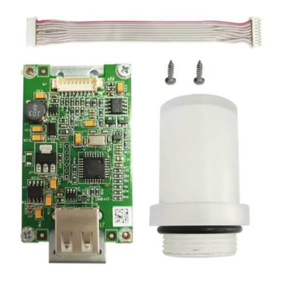
Page 2: Kit Contents
EN-1 1. INTRODUCTION Please read this manual completely before installation and operation. CAUTION: READ ALL SAFETY WARNINGS BEFORE INSTALLING, MAKING CONNECTIONS, OR SERVICING. FAILURE TO COMPLY WITH THESE WARNINGS COULD RESULT IN PERSONAL INJURY AND/OR PROPERTY DAMAGE. RETAIN ALL INSTRUCTIONS FOR FUTURE REFERENCE. 1.1 Kit Contents Battery with attached battery cover. -
Page 3: Installation Procedure
EN-2 2.2 Installation procedure Follow the steps below. Refer to the figures when performing these steps. For TD52P: Separate the indicator from the base by disconnecting the load cell cable from the male connector at the back of the Indicator. Remove the interface option cover. Interface option cover Load cell cable male connector Connect the 7-pin Li-ion Battery Pack power cable to the main board battery connector... - Page 4 EN-3 Place the Li-ion Battery Pack so Slots 1 on the bottom right edge of the Battery Pack align with the Rib on the bottom of the Indicator Option Area. Slide the Battery Pack to the right (in the direction of the arrow) until the Slots engage with the Rib. Slot 1 Arrow Boss post 9...
- Page 5 EN-4 For TD52XW: Remove the interface option cover. Release the 6 screws with sealed washers. Screw Load cell cable male connector Rotate the rear housing forward away from the front housing as shown. 1.800.561.8187 1.800.561.8187 information@itm.com information@itm.com www. www. .com .com...
- Page 6 EN-5 Connect the 7-pin Li-ion Battery Pack power cable to the main board battery connector as shown. Cable Battery connector Place the Li-ion Battery Pack so Slot 1 on the bottom right edge of the Battery Pack align with the Rib on the bottom of the Indicator Option Area. Slide the Battery Pack to the right (in the direction of the arrow) until the Slots engage with the Rib.
- Page 7 EN-6 Twist the Li-ion Battery Pack cable a half turn and connect the 7 Pin connector from the Indicator to the Battery Pack. Secure the Battery Pack with with one screw at the location marked Boss Screw 9. Connect the cable to Li battery packing 7 pin connectors. 7 Pin Connector Screw Put the rear housing back on the front housing.
- Page 8 EN-7 Take the rear housing down from the front housing as shown. Connect the cable to the main board battery connector 3. Cable Battery connector 3 1.800.561.8187 1.800.561.8187 information@itm.com information@itm.com www. www. .com .com...
- Page 9 EN-8 Install the Li battery packing. Push it along the arrow. (Note: slot 2 match with the rib of the red part). Slot 2 Boss post 10 Secure it with one screw (Note: Boss Post is 10). Connect the cable to Li battery packing 7 pin connectors.
-
Page 10: Battery Operation
EN-9 3. BATTERY OPERATION 3.1 Battery Icon During battery operation, the battery icon indicates the battery charge level remaining. Battery 5 - 25 % remaining Battery 25 - 50 % remaining Battery 50 - 75 % remaining Battery 75 - 100 % remaining The battery icon is located above the weighing unit on the indicator display, as can be seen in the image below. - Page 11 EN-10 WARNING: Stop charging the battery if charging is not completed within the specified time. Stop using the battery if the battery becomes abnormally hot, or if there is an oder, discoloration or deformation. Stop using the battery if abnormal conditions are detected during use, charging or storage.
Need help?
Do you have a question about the TD52 and is the answer not in the manual?
Questions and answers