OHAUS Defender 2000 Series Instruction Manual
Hide thumbs
Also See for Defender 2000 Series:
- Instruction manual (8 pages) ,
- Instruction manual (6 pages)

Related Manuals for OHAUS Defender 2000 Series


Summary of Contents for OHAUS Defender 2000 Series
- Page 1 2000 Series Indicators Instruction Manual T24PE Indicator Manual_Indicator_T24PE_V1...
-
Page 3: Table Of Contents
2000 Series Indicators EN-1 TABLE OF CONTENTS INTRODUCTION ............................EN-4 1.1 Definition of Signal Warnings and Symbols ....................EN-4 1.2 Safety Precautions .............................EN-4 1.3 Overview of Parts and Controls ........................EN-5 1.4 Control Functions ............................EN-8 INSTALLATION ............................EN-9 2.1 Unpacking ..............................EN-9 2.2 External Connections ..........................EN-9 2.2.1 Scale Base to Indicator ........................EN-9 2.2.2 AC Power to Indicator ........................EN-9 2.2.3 Battery power to Indicator .......................EN-10... - Page 4 EN-2 2000 Series Indicators TABLE OF CONTENTS (Cont.) 3.5 Readout Menu ............................EN-19 3.5.1 Reset ............................EN-19 3.5.2 Stable Range ..........................EN-20 3.5.3 Filter ............................EN-20 3.5.4 Auto-Zero Tracking ........................EN-20 3.5.5 Sleep ............................EN-20 3.5.6 Light ............................EN-20 3.5.7 Auto Off ............................EN-20 3.5.8 Expand ............................EN-20 3.5.9 End Readout ..........................EN-20 3.6 Mode Menu .............................EN-21 3.6.1 Reset ............................EN-21 3.6.2 Parts Counting Mode ........................EN-21...
- Page 5 2000 Series Indicators EN-3 TABLE OF CONTENTS (Cont.) 3.9 Security Switch ............................EN-25 OPERATION .............................EN-25 4.1 Turning Indicator On/Off ..........................EN-25 4.2 Zero Operation ............................EN-25 4.3 Manual Tare ............................EN-25 4.4 Changing Units of Measure ........................EN-26 4.5 Printing Data ............................EN-26 4.6 Application Modes ...........................EN-26 4.6.1 Weighing .............................EN-26 4.6.2 Parts Counting ..........................EN-26 4.6.3 Totalization ..........................EN-27...
-
Page 6: Introduction
EN-4 2000 Series Indicators INTRODUCTION This manual contains installation, operation and maintenance instructions for the T24PE indicator. Please read this manual completely before installation and operation. Definition of Signal Warnings and Symbols Safety notes are marked with signal words and warning symbols. These show safety issues and warnings. Ignoring the safety notes may lead to personal injury, damage to the instrument, malfunctions and false results. -
Page 7: Overview Of Parts And Controls
2000 Series Indicators EN-5 Overview of Parts and Controls TABLE 1-1. T24PE PARTS. Item Description Front Housing Control Panel Power Receptacle Load Cell Cable Connector RS232 Connector (optional) Data Label FCC Information Rear Housing Mounting Track Screw (4) Security Screw Figure 1-1. - Page 8 EN-6 2000 Series Indicators Overview of Parts and Controls (Cont.) Figure 1-2. Main PC Board. TABLE 1-2. MAIN PC BOARD. Item Description Power Connector J1 Battery Connector J9 Option Connector J2 LFT Switch 4-6 Lines Sense Jumper W1 (located on the other side of PCB) Load Cell Connector J4 4-6 Lines Sense Jumper W2 (located on the other side of PCB)
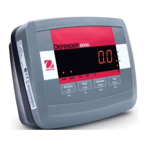
- Page 9 2000 Series Indicators EN-7 Overview of Parts and Controls (Cont.) Stable On/Zero Print Function Tare Units Mode Menu Figure 1-3. Controls and Indicators. TABLE 1-3. CONTROL PANEL. Designation Pound, Kilogram, Gram symbols Battery function symbol TARE Menu button FUNCTION Mode button Accumulation Symbol NET function symbol PRINT Units button...
-
Page 10: Control Functions
EN-8 2000 Series Indicators Control Functions TABLE 1-4. CONTROL FUNCTIONS. On/Zero Print Function Tare Units Mode Menu Button Back Exit ON/ZERO PRINT FUNCTION TARE Primary Function (Short Press) If Indicator is On, sets Sends the current value Initiates an application Performs a tare zero. -
Page 11: Installation
2000 Series Indicators EN-9 INSTALLATION Unpacking Unpack the following items: • Indicator • AC Adapter • Column Connector • Instruction Manual External Connections 2.2.1 Scale Base to Indicator Connect the load cell cable to the indicator as shown below: Connection +EXE +SEN +SIG -SIG -SEN -EXE Note: To connect T24PE to other bases, an optional loadcell connector (PN:30101021) needs to be purchased and soldered as shown above. 2.2.2 AC Power to Indicator Connect the AC Adapter to the power receptacle (Figure 1-1, item 3), then plug the AC Adapter into an electrical outlet. -
Page 12: Battery Power To Indicator
Approximately 30 minutes of operation will remain when the battery symbol starts to blink. The indicator will display Lo.BAT and automatically turn off when the battery is fully discharged. CAUTION BATTERY IS TO BE REPLACED ONLY BY AN AUTHORIZED OHAUS SERVICE DEALER. RISK OF EXPLOSION CAN OCCUR IF REPLACED WITH THE WRONG TYPE OR CONNECTED IMPROPERLY. -
Page 13: Internal Connections
2000 Series Indicators EN-11 Internal Connections Some connections require the housing to be opened. 2.3.1 Opening the Housing CAUTION: ELECTRICAL SHOCK HAZARD. REMOVE ALL POWER CONNECTIONS TO THE INDICATOR BEFORE SERVICING OR MAKING INTERNAL CONNECTIONS. THE HOUSING SHOULD ONLY BE OPENED BY AUTHORIZED AND QUALIFIED PERSONNEL, SUCH AS AN ELECTRICAL TECHNICIAN. Remove the four Phillips head screws from the rear housing. -
Page 14: Settings
EN-12 2000 Series Indicators SETTINGS Menu Structure TABLE 3-1. MENU STRUCTURE. CALIBRATION SETUP READOUT MODE UNIT PRINT END Zero RESET RESET RESET RESET RESET SPAN NO ... -
Page 15: Menu Navigation
2000 Series Indicators EN-13 Menu Navigation TO ENTER THE MENU MODE Press and hold the Menu button until MENU appears on the display. The first upper level menu appears on the display. Summary of button navigation functions in menu mode: --Yes Allows entry into the displayed menu. - Accepts the displayed setting and advances to the next menu item. -
Page 16: Span Calibration
EN-14 2000 Series Indicators 3.3.2 Span Calibration Span Calibration uses one point. The span point is established with a calibration mass placed on the scale. When SPAN is displayed, press the Yes button to access the Span Calibration menu item. The display flashes the span calibration point. -
Page 17: Geographical Adjustment Factor
2000 Series Indicators EN-15 3.3.4 Geographical Adjustment Factor The Geographcial Adjustment Factor (GEO) is used to compensate for variations in gravity. Attention: Changing the GEO Factor alters the calibration. The GEO value was set at the factory and should only be changed by an authorized manufacturer’s representative or certified verirication personnel. Refer to table 3-2 to determine the GEO factor that corresponds to your location. - Page 18 EN-16 2000 Series Indicators TABLE 3-2. GEOGRAPHICAL ADJUSTMENT VALUES Elevation in meters Geographical latitude 1300 1625 1950 2275 2600 2925 3250 away from the equator, 1300 1625 1950 2275 2600 2925 3250 3575 (North or South) in Elevation in feet 1060 2130 3200 4260 5330 6400...
-
Page 19: Setup Menu
2000 Series Indicators EN-17 Setup Menu When the Indicator is used for the first time, enter this Reset No, Yes menu to set the Capacity and Graduation. 5…20000 kg Capacity 0.0005…20 kg Graduation Power On Unit Auto, kg, g, lb Zero Range 2%, 100% End Setup... - Page 20 EN-18 2000 Series Indicators TABLE 3-3. SETUP AND CALIBRATION VALUES Full Capacity Graduation size(KG 1000~20000d) Span calibration points 0.0005,0.001,0.002,0.005 0.0005,0.001,0.002,0.005,0.01 5,10 0.001,0.002,0.005,0.01 5,10,15 0.001,0.002,0.005,0.01,0.02 5,10,15,20 0.002,0.005,0.01,0.02 5,10,15,20,25 0.002,0.005,0.01,0.02 5,10,15,20,25,30 0.002,0.005,0.01,0.02 5,10,15,20,25,30,40 0.005,0.01,0.02,0.05 5,10,15,20,25,30,40,50 0.005,0.01,0.02,0.05 5,10,15,20,25,30,40,50,60 0.005,0.01,0.02,0.05 5,10,15,20,25,30,40,50,60,75 0.005,0.01,0.02,0.05,0.1 5,10,15,20,25,30,40,50,60,75,100 0.01,0.02,0.05,0.1 5,10,15,20,25,30,40,50,60,75,100,120 0.01, 0.02,0.05,0.1 5,10,15,20,25,30,40,50,60,75,100,120,150...
-
Page 21: Graduation
2000 Series Indicators EN-19 3.4.3 Graduation Set the scale readability. 0.0005, 0.002, 0.005, 0.01, 0.02, 0.05, 0.1, 0.2, 0.5, 1, 2, 5, 10, 20. 0.0005 NOTE: Not all settings are available for each capacity. Refer to the Setup Table 3-3 for available settings. • • • pr.UNit 3.4.4 Power On Unit Set the unit that will be active at power on. Auto (last unit in use when power was turned off.), kg, g, lb UNIt 3.4.5 Zero Range... -
Page 22: Stable Range
EN-20 2000 Series Indicators 3.5.2 Stable Range StAbLE Set the stable range. 0.5d 3.5.3 Filter Set the amount of signal filtering. = less stability, faster stabilization time (<1 sec.) = normal stability, stabilization time (<2 sec.) = greater stability, slower stabilization time (<3 sec.) 3.5.4 Auto-Zero Tracking Set the automatic zero tracking functionality. -
Page 23: Mode Menu
2000 Series Indicators EN-21 Mode Menu Enter this menu to activate the desired application Reset: No, Yes modes. Count: Off, On Totalize: Off, On End Mode Exit MODE menu 3.6.1 Reset Set the Mode menu to the factory defaults. -
Page 24: Pound Unit
EN-22 2000 Series Indicators 3.7.3 Pound Unit UNIt Set the status. = Disabled = Enabled 3.7.4 End Unit Advance to the next menu. Print Menu (appears only with RS232 option installed) Enter this menu to define printing parameters. Default settings are bold. Reset No, Yes Baud Rate: 300, 600, 1200, 2400, 4800,... -
Page 25: Stop Bit
2000 Series Indicators EN-23 3.8.4 Stop Bit Set the number of stop bits. = 1 stop bit. = 2 stop bits. 3.8.5 Handshake Set the flow control method. NONE = no handshaking. ON-OFF = XON/XOFF software handshaking. 3.8.6 Stable Only Set the print critera. -
Page 26: Layout
EN-24 2000 Series Indicators LAYOUt 3.8.9 Layout Set the layout criteria. FOrmMt FORMAT mMULtI Multi = mutliple lines are printed. Single = single line is printed. SINGLE FEEd FEED Line = move paper up one line after printing. LINE 4 Lines = move paper up four lines after printing Form = move paper to top of next page (form feed) after printing. -
Page 27: Security Switch
2000 Series Indicators EN-25 3.9 Security Switch A security switch is located on the Main PCB board. When the switch is set to the on position, user menu settings that were locked in the Menu Lock can not be changed. Open the housing as explained in Section 2.3.1. -
Page 28: Changing Units Of Measure
EN-26 2000 Series Indicators Changing Units of Measure Press and hold the PRINT Units button until the desired measuring unit appears. Only measuring units enabled in the Unit Menu will be displayed (refer to Section 3.7). Printing Data Printing the displayed data to a printer or sending the data to a computer requires that the communication parameters in the Print Menu are set (refer to Section 3.8). Press the PRINT Units button to send the displayed data to the communication port (the Auto-Print Mode in Section 3.8 function must be Off). -
Page 29: Totalization
2000 Series Indicators EN-27 Recalling a Stored APW Press the No button to recall the existing APW. Press the FUNCTION Mode button to temporarily display the APW value. Establishing the Average Piece Weight (APW) The display shows Put10 Pcs. Establishing a New APW Press the No button to increment the sample size. -
Page 30: Serial Communication
EN-28 2000 Series Indicators SERIAL COMMUNICATION The Indicators include an RS232 serial communication interface. An optional RS232 serial communication interface can also be installed if required. Note: Some indicators does not include an RS232 serial communication interface. An optional RS232 serial communication interface (PN:30101019) needs to be purchased. The setup of RS232 operating parameters are more fully explained in Section 3.8. -
Page 31: Printout Examples
2000 Series Indicators EN-29 Printout Examples Weigh Mode Maximum 24 Description Comment characters 12.34 KG N PCS Result line ‘N’printed if a tare value is enteredesult line 12.34 KG G Gross value line If Print -> Content -> Gross is ON and a tare value is entered 11.11 KG N Net value line If Print ->... -
Page 32: Legal For Trade
EN-30 2000 Series Indicators LEGAL FOR TRADE Settings Enter the menu and perform a calibration as explained in Section 3 and then exit the Setup menu and power off the indicator. Open the housing as explained in Section 2.3.1. Set the position of the security switch, shown in Figure 1-2, to ON (item 4). Close the housing. -
Page 33: Maintenance
If the troubleshooting section does not resolve your problem, contact an authorized Ohaus Service Agent. For Service assistance in the United States, call toll-free 1-800-526-0659 between 8:00 AM and 5:00 PM Eastern Standard Time. An Ohaus Product Service Specialist will be available to assist you. Outside the USA, please visit our website www.ohaus.com to locate the Ohaus office nearest you. -
Page 34: Accessories
EN-32 2000 Series Indicators Ambient conditions The technical data is valid under the following ambient conditions: Indoor use only Ambient temperature: -10°C to 40°C / 14°F to 104°F Relative humidity: Maximum relative humidity 80% for temperatures up to 31°C decreasing linearly to 50% relative humidity at 40°C. Altitude: up to 2000m Mains supply voltage fluctuations: up to ±10% of the nominal voltage Installation category: II Pollution degree: 2... -
Page 35: Drawings And Dimensions
2000 Series Indicators EN-33 Drawings and Dimensions " 168 mm " " 8.26 3.28 210 mm 83.5 mm Figure 8-1. Indicator Overall Dimensions. -
Page 36: Compliance
This Class B digital apparatus complies with the Canadian ICES-003. This Class A digital apparatus complies with the Canadian ICES-003. Cet appareil numérique de la classe B est conforme à la Norme NMB-003 du Canada. Cet appareil numérique de la classe A est conforme à la Norme NMB-003 du Canada. ISO 9001 Registration In 1994, Ohaus Corporation, USA, was awarded a certificate of registration to ISO 9001 by Bureau Veritus Quality International (BVQI), confirming that the Ohaus quality management system is compliant with the ISO 9001 standard’s requirements. On May 21, 2009, Ohaus Corporation, USA, was re-registered to the ISO 9001:2008 standard. - Page 37 Ohaus. In lieu of a properly returned warranty registration card, the warranty period shall begin on the date of shipment to the authorized dealer.
- Page 39 Ohaus Corporation 7 Campus Drive Suite 310 Parsippany, NJ 07054, USA Tel: +1 (973) 377-9000 Fax: +1 (973) 944-7177 www.ohaus.com *30111429* P/N 30111429 A © 2015 Ohaus Corporation, all rights reserved. Printed in China...
Need help?
Do you have a question about the Defender 2000 Series and is the answer not in the manual?
Questions and answers