
Subscribe to Our Youtube Channel
Related Manuals for Hoymiles HME-1200-AU


Summary of Contents for Hoymiles HME-1200-AU
- Page 1 Open Energy for All Single-phase Microinverter USER MANUAL HME-1200-AU HME-1500-AU Region: Australia/New Zealand V202203 hoymiles.com...
- Page 2 Other Information Product information is subject to change without notice. This user manual will be frequently updated. Please refer to Hoymiles official website at www.hoymiles.com for the latest version. © 2022 Hoymiles Power Electronics Inc. All rights reserved.
-
Page 3: Table Of Contents
6.5 Routine Maintenance 6.6 Microinverter Replacement 7. Decommissioning 7.1 Decommissioning 7.2 Storage and Transportation 7.3 Disposal 8. Compliance Consideration 8.1 Earth Fault Alarm Notification 8.2 Power Quality Response Modes 8.3 DRM © 2022 Hoymiles Power Electronics Inc. All rights reserved. - Page 4 9.3 Efficiency, Safety and Protection 9.4 Mechanical Data 9.5 Features Appendix 1: Installation Map Appendix 2: WIRING DIAGRAM – 230 VAC SINGLE-PHASE: WIRING DIAGRAM – 230 VAC / 400 VAC THREE-PHASE: © 2022 Hoymiles Power Electronics Inc. All rights reserved.
-
Page 5: Important Notes
Indicates that the described operation must not be carried out. The reader should stop, use with caution and fully understand the operations explained before proceeding. © 2022 Hoymiles Power Electronics Inc. All rights reserved. -
Page 6: About Safety
Do not use the equipment if any anomalies are discovered while operating. Avoid temporary repairs. • All repairs should be carried out by using only qualified spare parts, which must be installed in accordance with their intended use and by a licensed contractor or authorized Hoymiles service representative. •... -
Page 7: Explanation Of Symbols
Increase the separation between the microinverter and the receiving antenna. Place a shield between the microinverter and the receiving antenna, such as a metal / concrete roof. Contact your dealer or an experienced radio/TV technician for help. © 2022 Hoymiles Power Electronics Inc. All rights reserved. -
Page 8: About Product
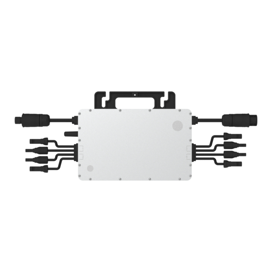
“Daisy-Chain 4-in-1 Unit Microinverter” with ultra-wide DC input operating voltage range (16 V–60 V) and low start-up voltage (22 V only). The Hoymiles 4-in-1 Unit Microinverter HME-1200/1500-AU is a reliable solution for PV systems with an uneven number of panels. -
Page 9: About Function
• The current condition contradicts with the microinverter operating requirements. • No household loads or the export control value has been set as “0” on the DTU in the Zero Export Control mode. © 2022 Hoymiles Power Electronics Inc. All rights reserved. -
Page 10: About Installation
UV, etc. Allow a minimum of 2 cm of space around the microinverter enclosure to ensure ventilation and heat dissipation. *Note: For some countries, the DTU will be required to meet local grid regulations Microinverter (e.g. G98/99 for UK). © 2022 Hoymiles Power Electronics Inc. All rights reserved. -
Page 11: Required Space Distance
PV modules to make sure that it operates in a shaded or shadowed environment. If this condition cannot be met, it may trigger the microinverter production de- rating. Fig.1 Microinverter installation position © 2022 Hoymiles Power Electronics Inc. All rights reserved. -
Page 12: Installation Steps
Part 3 AC Cable cable. 3. Plug the AC port Part 2 into Part 1 once the wiring is complete, then screw on Part 3 to complete the AC extension cable. © 2022 Hoymiles Power Electronics Inc. All rights reserved. - Page 13 Step 9. Installation and Selection of an External RCD device Installation of an RCD must always be conducted in accordance with local codes and standards. Hoymiles recommends the use of a type-A RCD for Australia and New Zealand and a 30mA RCD is suggested for our Single-phase microinverters.
-
Page 14: Troubleshooting
Single-phase Microinverter User Manual 6. Troubleshooting This microinverter can only work with the new Hoymiles DTU (DTU-Pro, DTU-Lite and DTU-W100/DTU-G100) with the following serial number. Model Serial Number 10F7xxxxxxxx DTU-Pro 10F8xxxxxxxx 10FAxxxxxxxx DTU-G100 10D2xxxxxxxx DTU-W100 10D3xxxxxxxx DTU-Lite 10D6xxxxxxxx Troubleshooting List... - Page 15 2. If the alarms occur frequently on all the microinverters in your Island detected station, contact the local power operator to check whether there is a grid island. 3. If the alarm still exists, contact your dealer or Hoymiles Technical Service Center. © 2022 Hoymiles Power Electronics Inc. All rights reserved.
- Page 16 1. If the alarm occurs accidentally and the microinverter can still function normally, no special treatment is required. Hardware error code 305 2. If the alarm occurs frequently and cannot be restored, contact your dealer or Hoymiles Technical Service Center. © 2022 Hoymiles Power Electronics Inc. All rights reserved.
- Page 17 1. If the alarm occurs accidentally and the microinverter can still function normally, no special treatment is required. Hardware error code 308 2. If the alarm occurs frequently and cannot be restored, contact your dealer or Hoymiles Technical Service Center. © 2022 Hoymiles Power Electronics Inc. All rights reserved.
-
Page 18: Status Led Indicator
(3) Other Status • Alternating red and green flashing: Firmware is corrupted. *Note: All faults are reported to the DTU, refer to the local DTU app or S-Miles Cloud (Hoymiles Monitoring Platform) for more information. Insulation Resistance Detection There is a resistance sensor in the microinverter to measure the resistance between the outputs of PV module and the ground. -
Page 19: On-Site Inspection (For Qualified Installer Only)
Avoid temporary repairs. All repairs should be carried out by using only genuine spare parts. If all microinverters connect to the DTU-Pro, the DTU can limit the output power imbalance of all microinverters between phases to below 3.68 kW if required. Please refer to the “Hoymiles Technical Note Limit Phase Balance” for more details. -
Page 20: Microinverter Replacement
“Devices” page to find the device that you just replaced. Click the “Device Maintenance” button to jump to the new page and select “Replace Device”. Enter the new microinverter’s SN and click the “OK” button to complete the replacement. © 2022 Hoymiles Power Electronics Inc. All rights reserved. -
Page 21: Decommissioning
Storage and Transportation Hoymiles packages and protects individual components by using suitable means to facilitate the transport and subsequent handling. Transportation of the equipment, especially by road, must be carried out by using means that are suitable for protecting the components (in particular, the electronic components) from violence, shocks, humidity, vibration, etc. -
Page 22: Compliance Consideration
Operating Guide (Webpage) V2.0” and “HMP Operation Guide (APP)” or contact Tech Support for more information. And please refer to “Technical Note-How to set Hoymiles 3Gen Grid Profile V1.1” for more details about the gridprofile. DRM is provided to support several demand response modes by giving control signals as below. -
Page 23: Technical Data
DC short-circuit current. The output DC power of the PV module is NOT recommended to exceed 1.35 times the output AC power of the microinverter. Refer to the “Hoymiles Warranty Terms & Conditions” for more information. -
Page 24: Efficiency, Safety And Protection
*2 Refer to local requirements for exact number of microinverters per branch. *3 Hoymiles Monitoring System *Note: Voltage and frequency ranges can be extended beyond nominal if required by the utility. © 2022 Hoymiles Power Electronics Inc. All rights reserved. -
Page 25: Installation Map
To sheet Hoymiles Microinverter Installation Map AP040228 V1.4 Please Make N for North Panel type: Customer Information: DTU Serial Number Azimuth: Tilt: Sheet COLUMN To sheet... -
Page 26: Wiring Diagram - 230 Vac Single-Phase
AC BRANCH CABLE AC BRANCH CABLE BROWN - L BROWN - L BLUE - N UP TO 3 HM-1500s PER BLUE - N UP TO 3 HM-1500s PER YELLOW&GREEN - G YELLOW & GREEN - G AC BRANCH CIRCUIT AC BRANCH CIRCUIT AC DISTRIBUTION PANEL OR AC DISTRIBUTION PANEL OR SUBPANEL... -
Page 27: Wiring Diagram - 230 Vac / 400 Vac Three-Phase
UP TO 3 HM-1500s PER UP TO 3 HM-1500s PER AC BRANCH CABLE AC BRANCH CABLE AC BRANCH CIRCUIT AC BRANCH CIRCUIT BROWN - L BROWN - L BLUE - N BLUE - N YELLOW & GREEN - G YELLOW&GREEN - G PHASE-L1 PHASE-L1 AC DISTRIBUTION PANEL...
Need help?
Do you have a question about the HME-1200-AU and is the answer not in the manual?
Questions and answers