Table of Contents
Advertisement
Quick Links
Advertisement
Table of Contents

Related Manuals for Hoymiles HME-1000T-AU


Summary of Contents for Hoymiles HME-1000T-AU
- Page 1 Version 1.2 (June 2020)
- Page 2 Other Information Product information is subject to change without notice. User manual will be updated frequently, please refer to Hoymiles official website at www.hoymiles.com for the latest version. © 2019 Hoymiles Converter Technology Co., Ltd. All rights reserved.
-
Page 3: Table Of Contents
6.4 Routine Maintenance ..........................19 6.5 Replace Microinverter ..........................20 7. Decommissions ..............................21 7.1 Decommissions ............................21 7.2 Storage and Transportation ........................21 7.3 Disposal ..............................21 8. Compliance Consideration ..........................22 © 2019 Hoymiles Converter Technology Co., Ltd. All rights reserved. - Page 4 Appendix 1: ................................26 Installation Map ..............................26 Appendix 2: ................................27 WIRING DIAGRAM – 230VAC SINGLE PHASE: ..................27 WIRING DIAGRAM – 230VAC / 400VAC THREE PHASE: ............... 28 © 2019 Hoymiles Converter Technology Co., Ltd. All rights reserved.
-
Page 5: Important Notes
However, certain safety precautions must be taken when installing and operating this inverter. The installer must read and follow all instructions, cautions and warnings in this installation manual. © 2019 Hoymiles Converter Technology Co., Ltd. All rights reserved. -
Page 6: Explanation Of Symbols
Ø Do not use the equipment if any operating anomalies are found. Avoid temporary repairs. Ø All repairs should be carried out using only qualified spare parts, which must be installed in accordance with their intended use and by a licensed contractor or authorized Hoymiles service representative. -
Page 7: Radio Interference Statement
“The world’s First Daisy-Chain 4 in 1 Unit Microinverter” with extremely wide DC input operating voltage range (16-60V) and low start-up voltage (22V only). Hoymiles 4 in 1 unit Microinverter HME-1000T/1200T/1350T/1500T-AU is the perfect selection for PV system with uneven number of panels with world’s NO.1 CEC weighted efficiency – 96.50% (peak efficiency 96.70%) in 2015. -
Page 8: Highlights
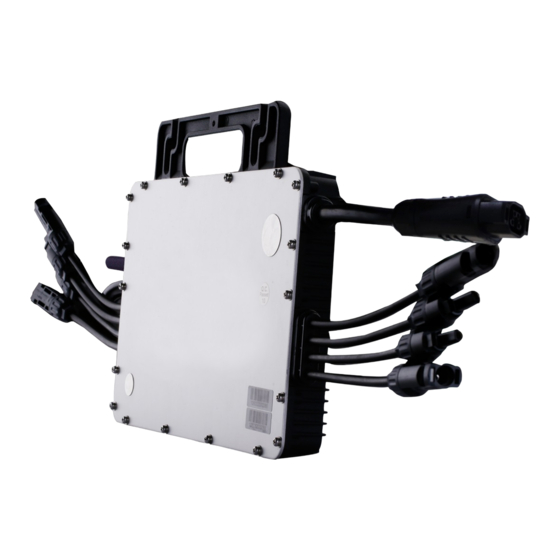
Power factor (adjustable) 0.8 leading……0.8 lagging. External antenna for stronger communication with DTU. High reliability: NEMA6 (IP67) enclosure; 6000V surge protection. 3.3 Terminals Introduction Objec Description 2.4GHz Antenna DC Connector AC Connectors 3.4 Dimension(mm) © 2019 Hoymiles Converter Technology Co., Ltd. All rights reserved. -
Page 9: About Function
*Note: All accessories above are not included in the package, and need to be purchased separately. Please contact our sales representative for the price. (M8 screws need to be prepared by installer-self.) © 2019 Hoymiles Converter Technology Co., Ltd. All rights reserved. -
Page 10: Installation Precaution
Under such installation conditions, it is better for the microinverters to be installed 50cm above the roof. Otherwise, more DTUs may be required to ensure the communication quality between the DTUs and the microinverters. © 2019 Hoymiles Converter Technology Co., Ltd. All rights reserved. -
Page 11: Preparation
Install Microinverter underneath of the photovoltaic modules to make sure it works in theshadow. If this condition cannot be met, might trigger the inverter production de-rating. Fig.1 Installation position of microinverter © 2019 Hoymiles Converter Technology Co., Ltd. All rights reserved. -
Page 12: Installation Steps
A) Hang the microinverter on the screw (shown as picture below), and tighten the screw.The silver cover side of the Microinverter should be facing the panel. *Note: Please install the microinverter at least 50cm above the ground/roof for better communication with Hoymiles DTU. - Page 13 A) Peel the removable serial number lable from each microinverter (The position of the label is shown as below). B) Affix the serial number label to the respective location on the installation map. © 2019 Hoymiles Converter Technology Co., Ltd. All rights reserved.
-
Page 14: Troubleshooting
Hoymiles technical support. 1.Check if the grid configuration parameter is correct and upgrade again. Grid configuration 2. If the fault still exists, contact your dealer or Hoymiles technical parameter error support. © 2019 Hoymiles Converter Technology Co., Ltd. All rights reserved. - Page 15 DTU and microinverter. Then try Firmware error again. 3. If the fault still exists, contact your dealer or Hoymiles technical support. 1. If the alarm occurs accidentally and the microinverter can still work Software error code normally, no special treatment is required.
- Page 16 2. If the alarm occurs frequently, check whether the grid frequency change rate change rate is within the acceptable range. If no, contact the local power operator or change the grid frequency change rate limit via Hoymiles monitoring system with the consent of the local power operator. Power grid outage Please check whether there is a power grid outage.
- Page 17 1. If the alarm occurs accidentally and the microinverter can still work Hardware Error Code normally, no special treatment is required. 2. If the alarm occurs frequently and cannot be recovered, contact your dealer or Hoymiles technical support. © 2019 Hoymiles Converter Technology Co., Ltd. All rights reserved.
-
Page 18: Status Led Indicator
ü Flashing Red and Green alternately: Firmware is corrupted. *Note: All the faults are reported to the DTU, refer to the local APP of the DTU or Hoymiles Monitoring Platform for more information. 6.3 On-site Inspection (For qualified installer only) To troubleshoot an inoperable microinverter, follow the steps in the order shown. -
Page 19: Routine Maintenance
5. Check the DC connections between the microinverter and the PV module. 6. Verify the PV module DC voltage is within the allowable range shown in appendix Technical Data of this manual. 7. If the problem persists, please call Hoymiles customer support. Warning Ø... -
Page 20: Replace Microinverter
Avoid temporary repairs. All repairs should be carried out using only genuine spare parts. If all the microinverters connect to the DTU-Pro, the DTU can limit the output power imbalance of all the microinverters between phases to below 3.68kW if required. Please refer to “Hoymiles Technical Note Limit Phase Balance” for more details. -
Page 21: Decommissions
7.2 Storage and Transportation Hoymiles packages and protects individual components using suitable means to make the transport and subsequent handling easier. Transportation of the equipment, especially by road, must be carried out by suitable ways for protecting the components (in particular, the electronic components) from violent, shocks, humidity, vibration, etc. -
Page 22: Compliance Consideration
An external indication of earth fault alarm can be provided by the connecting the PV System to Hoymiles monitoring app/portal. For details of how to configure monitoring please refer to document “HMP Operating Guide (Webpage) V2.0” and “HMP Operation Guide (APP)”. -
Page 23: Technical Data
DC current. But the maximum short circuit current must be equal to or less than the maximum input DC short circuit current. The output DC power of PV module is NOT recommended to exceed 1.35 times the output AC power of the microinverter. Refer to “Hoymiles Warranty Terms & Conditions” for more information. 8.1 DC Input Model... -
Page 24: Efficiency, Safety And Protection
12 years standard, 25 years optional VDE-AR-N 4105:2018, EN50549-1:2019, VFR2019, Compliance AS 4777.2:2015, IEC/EN 62109-1/-2, IEC/EN 61000-3-2/-3, IEC/EN-61000-6- 1/-2/-3/-4 *Note: Nominal voltage/frequency range can be changed due to the requirements of local power department © 2019 Hoymiles Converter Technology Co., Ltd. All rights reserved. - Page 25 HME-1000T/1200T/1350T/1500T-AU © 2019 Hoymiles Converter Technology Co., Ltd. All rights reserved.
-
Page 26: Installation Map
HME-1000T/1200T/1350T/1500T-AU Appendix 1: Installation Map © 2019 Hoymiles Converter Technology Co., Ltd. All rights reserved. -
Page 27: Wiring Diagram - 230Vac Single Phase
HME-1000T/1200T/1350T/1500T-AU Appendix 2: WIRING DIAGRAM – 230VAC SINGLE PHASE: © 2019 Hoymiles Converter Technology Co., Ltd. All rights reserved. -
Page 28: Wiring Diagram - 230Vac / 400Vac Three Phase
HME-1000T/1200T/1350T/1500T-AU WIRING DIAGRAM – 230VAC / 400VAC THREE PHASE: © 2019 Hoymiles Converter Technology Co., Ltd. All rights reserved.
Need help?
Do you have a question about the HME-1000T-AU and is the answer not in the manual?
Questions and answers