
Related Manuals for Hoymiles HMS-1600-4T-NA


Summary of Contents for Hoymiles HMS-1600-4T-NA
- Page 1 Open Energy for All Single-phase Microinverter USER MANUAL HMS-1600-4T-NA HMS-1800-4T-NA HMS-2000-4T-NA Region: North America V202201 hoymiles.com...
- Page 2 Other Information Product information is subject to change without notice. User manual will be updated regularly, so please refer to Hoymiles official website at www.hoymiles.com for the latest version. © 2022 Hoymiles Power Electronics Inc. All rights reserved.
-
Page 3: Table Of Contents
8. Technical Data 9. Grid Support Details 10. Appendix 1: 10.1 Installation Map 11. Appendix 2: 11.1 WIRING DIAGRAM –120VAC / 240VAC SPLIT PHASE: 11.2 WIRING DIAGRAM – 120VAC / 208VAC THREE PHASE: © 2022 Hoymiles Power Electronics Inc. All rights reserved. -
Page 4: Important Notes
*Note: “1600” means peak power 1600 W, “1800” means peak power 1800 W, “2000” means peak power 2000 W. “NA” means this model is for North America. *Note: HMS-1600/1800/2000-4T-NA is only compatible with Hoymiles gateway DTU-Pro-S and DTU-Lite-S. 1.2 Target Group This manual is only for qualified technicians. -
Page 5: About Safety
• intended use and by a licensed contractor or authorized Hoymiles service representative. • Liabilities arising from components that are not produced by Hoymiles are on the part of their re- spective manufacturers. • Whenever the inverter has been disconnected from the public grid, please be extremely careful as some components can retain charge sufficient to create a shock hazard. -
Page 6: Explanation Of Symbols
The inverter complies with the Low Voltage Directive for the European Union. FCC mark The inverter complies with the FCC standards. Read manual first Please read the installation manual first before installation, operation and main- tenance. © 2022 Hoymiles Power Electronics Inc. All rights reserved. -
Page 7: About Product
Hoymiles microinverters feature module-level monitoring and maintenance. Microinverter data and information are collected by Hoymiles gateway DTU via wireless transmission and are sent to Hoymiles monitoring system S-Miles Cloud. © 2022 Hoymiles Power Electronics Inc. All rights reserved. -
Page 8: About 4-In-1 Unit
Sub-1G Microinverter This manual is about Hoymiles 4-in-1 microinverter. With the peak output power up to 2000 VA, Hoymiles new HMS-2000 series rank among the highest for 4-in-1 microinverters. Each microinverter connects to four PV modules at most with independent MPPT and monitoring, enabling greater energy harvest and easier maintenance. -
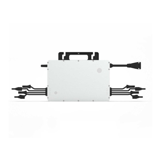
Page 9: Terminals Introduction
Single-phase Microinverter HMS-1600/1800/2000-4T-NA About Product / Installation Preparation 3.6 Terminals Introduction Object Description Sub-1G Wireless Terminal DC Connectors AC Sub Connector 3.7 Dimensions (mm) © 2022 Hoymiles Power Electronics Inc. All rights reserved. -
Page 10: Installation Preparation
Note: The voltage of modules (considering the effect of local temperature) must not exceed the maximum input voltage of the microinverter. Otherwise, the microinverter may be damaged (refer to the Technical Data section to determine the absolute maximum input voltage). © 2022 Hoymiles Power Electronics Inc. All rights reserved. -
Page 11: Installation Tools
Hoymiles HMS-1600-4T-NA/HMS-1800-4T-NA/HMS-2000-4T-NA can be used with 12AWG or 10AWG AC Trunk Cable and the AC Trunk Connector which are provided by Hoymiles. The number of microinverters on each 12AWG or 10AWG AC branch shall not exceed the limit as shown below. -
Page 12: Precautions
Install only on structures specifically designed for PV modules (supplied by installation technicians). • • Install microinverter underneath PV modules to make sure it works in the shadow. Nonobservance may cause the derating of inverter production. © 2022 Hoymiles Power Electronics Inc. All rights reserved. -
Page 13: Microinverter Installation
B ) Fix the screws on the rail. Mounting Torque : 9 N·m C ) Hang the microinverter on the screws, and tighten the screws. The silver cover side of the microinverter should be facing the panel. © 2022 Hoymiles Power Electronics Inc. All rights reserved. - Page 14 A ) Select the appropriate AC Trunk Cable according to the spacing between microinverters. The connec- tors of the AC Trunk Cable should be spaced based on the spacing between microinverters to ensure that they can properly matched. (Hoymiles provides AC Trunk Cable with different AC Trunk Connec- tor spacing.) B ) Determine how many microinverters you plan to install on each AC branch and prepare AC Trunk Connectors accordingly.
- Page 15 Trunk connectors. E ) Attach the AC Trunk Cable to the mounting rail and fix the cable with tie wraps. © 2022 Hoymiles Power Electronics Inc. All rights reserved.
- Page 16 Refer to the “DTU User Manual”, “DTU Quick Installation Guide”, and “Quick Installation Guide for S-Miles Cloud” to install the DTU and set up the monitoring system. Product information is subject to change without notice. (Please download reference manuals at www.hoymiles.com) © 2022 Hoymiles Power Electronics Inc. All rights reserved.
-
Page 17: Troubleshooting
1.Check if the grid configuration parameter is correct and Grid configuration upgrade. parameter error 2. If the fault still exists, contact your dealer or Hoymiles technical support team. 1.Check if the firmware is correct and has been upgraded. 2.Check the communication between DTU and Hoymiles monitoring system, and between DTU and microinverter. - Page 18 If not, contact the local power operator or change the grid undervoltage protection limit in the grid profile via Hoymiles monitoring system with the consent of the local power operator. 3. If the fault still exists, check the AC switch or AC wiring.
- Page 19 MPPT-B Input undervoltage 2. If the PV module open-circuit voltage is within the normal range, contact your dealer or Hoymiles technical support team. 1. Please confirm whether this port is connected to the PV module. PV-1 No input 2.
-
Page 20: Led Indicator Status
1. The microinverter is powered by DC side. If the LED light is not on, please check the DC side connection. If the connection and input voltage are normal, contact your dealer or hoymiles technical support team. 2. All the faults are reported to the DTU. Refer to the local DTU app or Hoymiles Monitoring Platform for more information. -
Page 21: On-Site Inspection (For Qualified Installer Only)
Make sure that PV modules’ DC voltage is within the allowable range shown in the Technical Data section of this manual. If the problem persists, please call Hoymiles customer support. Do not try to repair the microinverter by yourself. If the troubleshooting fails, please return it to the factory for replacement. -
Page 22: Microinverter Replacement
“Device List” page and find the device that you just replaced. Please click “Device Maintenance” on the right side of the page, and select “Replace Device”. Input the new microinverter’s SN and click “Ok” to complete the station change. © 2022 Hoymiles Power Electronics Inc. All rights reserved. -
Page 23: Decommission
5 kg and can be fully closed. 7.2 Storage and Transportation Hoymiles packages are specially designed to protect components so as to facilitate transportation and subsequent handling. Transportation of the equipment, especially by road, must be done in a way that can protect the components (particularly the electronic components) from violent shocks, humidity, vibration, etc. -
Page 24: Technical Data
Single-phase Microinverter HMS-1600/1800/2000-4T-NA Technical Data 8. Technical Data Be sure to verify the following before installing Hoymiles Microinverter System. 1. Verify that the voltage and current specifications of the PV module match those of the microinverter. • The maximum open circuit voltage rating of the PV module must be within the operating voltage range of the microinverter. -
Page 25: Grid Support Details
Grid Support Utility Interactive Inverter. And these microinverters also comply with California Rule 21. The Grid Support functions are controlled on Hoymiles Monitoring Platform and the DTU is required in this PV system. - Page 26 Unit Tolerance %Irated/s +/-4% Ramp up rate Soft ramp up %Irated/s +/-4% rate SA12: Specified Power Factor (SPF) Adjustment Range Inductive, under excited, power factor -0.8 -1.0 Capacitive, overexcited, power factor © 2022 Hoymiles Power Electronics Inc. All rights reserved.
- Page 27 SA15: Volt-Watt (VW) Unit HMS-1600-4T-NA HMS-1800-4T-NA HMS-2000-4T-NA Output power rating 1440 1660 1918 %Prated Output Power accuracy %Prated/ Maximum slope of active power reduction %Prated/ Minimum slope of active power reduction © 2022 Hoymiles Power Electronics Inc. All rights reserved.
-
Page 28: Appendix
Single-phase Microinverter HMS-1600/1800/2000-4T-NA 10. Appendix 1: 10.1 Installation Map © 2022 Hoymiles Power Electronics Inc. All rights reserved. -
Page 29: Appendix
Single-phase Microinverter HMS-1600/1800/2000-4T-NA 11. Appendix 2: 11.1 WIRING DIAGRAM –120VAC / 240VAC SPLIT PHASE: © 2022 Hoymiles Power Electronics Inc. All rights reserved. -
Page 30: Wiring Diagram - 120Vac / 208Vac Three Phase
Single-phase Microinverter HMS-1600/1800/2000-4T-NA 11. Appendix 2: 11.2 WIRING DIAGRAM – 120VAC / 208VAC THREE PHASE: © 2022 Hoymiles Power Electronics Inc. All rights reserved.
Need help?
Do you have a question about the HMS-1600-4T-NA and is the answer not in the manual?
Questions and answers