Table of Contents
Advertisement
Quick Links
Advertisement
Table of Contents

Subscribe to Our Youtube Channel
Related Manuals for Solplanet ASW LT-G3 Series


Summary of Contents for Solplanet ASW LT-G3 Series
-
Page 2: Table Of Contents
ASW LT-G3 series inverter Table of Contents 1 Notes on this Manual ......................4 1.1 General Notes ......................... 4 1.2 Area of Validity ........................ 4 1.3 Target group ........................5 1.4 Symbols used in this manual ..................6 2 Safety ............................7 2.1 Intended use ........................ - Page 3 5.5.1 Requirements for the DC connetion ..............30 5.5.2 Assembling the DC connectors ................31 5.5.3 Disassembling the DC connectors ..............33 5.5.4 Connecting the PV Array ..................35 5.6 Conmunication equipment connection ............... 37 5.6.1 Connect the communication line with RJ45 socket ......... 37 5.6.2 Mounting the COM3: WiFi/4G ................
- Page 4 10.3 General data ........................ 58 10.4 Safety regulations ....................... 60 10.5 Tools and torque ......................61 11 Troubleshooting ........................63 12 Maintenance ........................66 12.1 Cleaning the contacts of the DC-switch ..............66 12.2 Cleaning the heat sink....................66 13 Recycling and disposal ...................... 67 14 EU Declaration of Conformity ...................
-
Page 5: Notes On This Manual
1 Notes on this Manual 1.1 General Notes ASW LT-G3 series inverter is a three-phase transformerless string inverter with three to three independent MPPTs. It converts the direct current (DC) generated by the photovoltaic (PV) module into a three-phase alternating current (AC) and feeds it into the utility grid. -
Page 6: Target Group
1.3 Target group This document is for qualified electricians only, who must perform the tasks exactly as described. All persons installing inverters must be trained and experienced in general safety which must be observed when working on electrical equipment. Installation personnel should also be familiar with local requirements, rules and regulations. -
Page 7: Symbols Used In This Manual
1.4 Symbols used in this manual Safety instructions will be highlighted with the following symbols: DANGER indicates a hazardous situation which, if not be avoided, will result in death or serious injury. WARNING indicates a hazardous situation which, if not be avoided, can result in death or serious injury. -
Page 8: Safety
2 Safety 2.1 Intended use 1. ASW LT-G3 series inverter converts the direct current from the PV arrays into grid-compliant alternating current. 2. ASW LT-G3 series inverter is suitable for indoor and outdoor use. 3. ASW LT-G3 series inverter must only be operated with PV arrays (PV modules and cabling) of protection class II in accordance with IEC 61730, application class A. -
Page 9: Important Safety Information
2.2 Important safety information Danger to life due to electric shock when live components or cables are touched • All work on the inverter must only be carried out by qualified personnel who have read and fully understood all safety information contained in this manual. - Page 10 Risk of injury due to electric shock Touching an ungrounded PV module or array frame can cause a lethal electric shock. • connect and ground the PV modules, array frame and electrically conductive surfaces so that there is continuous conduction. Risk of burns due to hot enclosure parts Some parts of the enclosure can get hot during operation.
-
Page 11: Symbols On The Label
2.3 Symbols on the label Explanation Symbol Beware of a danger zone This symbol indicates that the inverter must be additionally grounded if additional grounding or equipotential bonding is required at the installation site. Beware of high voltage and operating current The inverter operates at high voltage and current. - Page 12 capacitors to fully discharge. Observe the documentation Observe all documentation supplied with the product User Manual UM0016_ASW 25K-40K-LT-G3_EN_V02_0622...
-
Page 13: Unpacking
3 Unpacking 3.1 Scope of delivery Obje Description Quantity Inverter 1 piece Wall mounting bracket 1 piece DC connector 2 pieces Screw accessory 1 piece AC connector 1 piece 4G/ WiFi Stick (optional) 1 piece(optional) RS485 communication terminal 1 piece(optional) Documentation 1 piece Please carefully check all the components in the carton. -
Page 14: Mounting
4 Mounting 4.1 Requirements for mounting Danger to life due to fire or explosion Despite careful construction, electrical devices can cause fires. • Do not mount the inverter on flammable construction materials. • Do not mount the inverter in areas where flammable materials are stored. - Page 15 Clearances for one inverter Clearances for multiple inverters User Manual UM0016_ASW 25K-40K-LT-G3_EN_V02_0622...
- Page 16 6. In order to avoid power reduction caused by overheating, do not mount the inverter in a location that allows long-term exposure to direct sunlight. 7. Ensure optimum operation and extend service life, avoid exposing the inverter to direct sunlight, rain and snow. 8.
- Page 17 12. Never install the inverter horizontally, or with a forward tilt or with a backward tilt or even with upside down. The horizontal installation can result in damage to the inverter. 13. Mount the inverter at eye level for easy inspection. User Manual UM0016_ASW 25K-40K-LT-G3_EN_V02_0622...
-
Page 18: Mounting The Inverter
4.2 Mounting the inverter Risk of injury when lifting the inverter, or if it is dropped The weight of Solplanet inverter is max. 43 kg. There is risk of injury if the inverter is lifted incorrectly or dropped while being transported or when attaching it to or removing it from the wall bracket. - Page 19 Risk of injury due to the product falls down If the depth and distance of the holes is not correct, the product maybe fall down from the wall. •Before inserting the wall anchors, measure the depth and distance of the holes. 2.
- Page 20 3. Hang the slot on the back of the inverter to the hook on the top of the mounting bracket. 4. Secure the inverter to the mounting bracket on both sides using two M5 screws. Screwdriver type:PH2, torque:2.5Nm. User Manual UM0016_ASW 25K-40K-LT-G3_EN_V02_0622...
- Page 21 Dismante the inverter in reverse order. User Manual UM0016_ASW 25K-40K-LT-G3_EN_V02_0622...
-
Page 22: Electrical Connection
5 Electrical connection 5.1 Safety Danger to life due to high voltages of the PV array When exposed to sunlight, the PV array generates dangerous DC voltage which is present in the DC conductors and the live components of the inverter. Touching the DC conductors or the live components can lead to lethal electric shocks. -
Page 23: Electrical Connection Panel
5.2 Electrical Connection Panel Object Description DC-switch MPP connector Communication interface(COM1 & COM2 are optional) AC terminal Additional grounding 5.3 Electrical connection diagram with a separate DC isolator Local standards or codes may require that a separate DC isolator should be installed next to the inverter. The separate DC isolator must disconnect each PV string of the inverter so that the entire inverter can be removed if the inverter is faulty. -
Page 24: Ac Connection
5.4 AC Connection 5.4.1 Conditions for the AC connection Cable Requirements The grid connection is made using 5 conductors (L1, L2, L3, N, and PE). We recommend the following requirements for stranded copper conductor. 1. YJV or YJVR copper cable is recommended. 2. - Page 25 Object Description Value External diameter 20…36 mm Copper Conductor cross-section 10…25 mm Note: If use aluminuim conductor please connect our service department. Cable Design The conductor cross-section should be dimensioned to avoid power loss in cables exceeding 1% of rated output power. The required conductor cross-section depends on the inverter rating, ambient temperature, routing method, cable type, cable losses, valid installation requirements of installation side.
- Page 26 If an external residual-current protection device is required, please install a type B residual-current protection device with a protection limit of not less than 300mA. Overvoltage category The inverter can be used in grids of overvoltage category III or lower in accordance with IEC 60664-1. This means that it can be permanently connected at the grid-connection point in a building.
- Page 27 The inverter is equipped with a grounding conductor monitoring device. This grounding conductor monitoring device detects when there is no grounding conductor connected and disconnects the inverter from the utility grid if this is the case. Depending on the installation site and grid configuration, it may be advisable to deactivate the grounding conductor monitoring.
-
Page 28: Grid Connection
5.4.2 Grid connection Procedure: Danger to life due to high voltages in the inverter Touching the live components can lead to lethal electric shocks. • Before performing the electrical connection, ensure that the AC circuit-breaker is switched off and cannot be reactivated. 1. - Page 29 4. Insert the main body into the rubber core and hear the "click" sound. 5. Tighten the nut with an open-ended wrench and complete the installation with a "click, click, click", then complete the installation. User Manual UM0016_ASW 25K-40K-LT-G3_EN_V02_0622...
-
Page 30: Additional Grounding Connection
5.4.3 Additional grounding connection If additional grounding or equipotential bonding is required locally, you can connect additional grounding to the inverter. This prevents touch current if the grounding conductor on the AC connector fails. Procedure: 1. Align the terminal lug with protective conductor. 2. -
Page 31: Dc Connection
5.5 DC connection Danger to life due to high voltages in the inverter Touching the live components can lead to lethal electric shocks. • Before connecting the PV generator, ensure that the DC- switch is switched off and that it cannot be reactivated. •... -
Page 32: Assembling The Dc Connectors
5.5.2 Assembling the DC connectors Danger to life due to high voltages on DC conductors When exposed to sunlight, the PV array generates dangerous DC voltage which is present in the DC conductors. Touching the DC conductors can lead to lethal electric shocks. •... - Page 33 2. Route the stripped cable all the way into the DC connector. Ensure that the stripped cable and the DC connector have the same polarity. 3. Push the swivel nut up to the thread and tighten the swivel nut. (SW15, Torque: 2.0Nm) User Manual UM0016_ASW 25K-40K-LT-G3_EN_V02_0622...
-
Page 34: Disassembling The Dc Connectors
5.5.3 Disassembling the DC connectors Danger to life due to high voltages on DC conductors When exposed to sunlight, the PV array generates dangerous DC voltage which is present in the DC conductors. Touching the DC conductors can lead to lethal electric shocks. •... - Page 35 6. Remove the cable. User Manual UM0016_ASW 25K-40K-LT-G3_EN_V02_0622...
-
Page 36: Connecting The Pv Array
5.5.4 Connecting the PV Array Destruction of the inverter due to overvoltage If the voltage of the strings exceeds the maximum DC input voltage of the inverter, it can be destroyed due to overvoltage. All warranty claims become void. • Do not connect strings with an open-circuit voltage greater than the maximum DC input voltage of the inverter. - Page 37 Damage to the inverter due to moisture and dust penetration Seal the unused DC inputs with sealing plugs so that moisture and dust cannot penetrate the Inverter. • Make sure all DC connectors are securely sealed. User Manual UM0016_ASW 25K-40K-LT-G3_EN_V02_0622...
-
Page 38: Conmunication Equipment Connection
5.6 Conmunication equipment connection 5.6.1 Connect the communication line with RJ45 socket Damage to the inverter due to electrostatic discharge Internal components of the inverter can be irreparably damaged by electrostatic discharge. • Ground yourself before touching any component. The inverter can be destroyed by wrong communication wiring •... - Page 39 RS485 cable pin assignment as below, strip the wire as shown in the figure, and crimp the copper wire to the appropriate OT terminal (according to DIN 46228-4, provided by the customer). Procedure: 1. Unscrew the communication port cover cap in the following arrow sequence and insert the network cable into the RS485 communication client attached.
-
Page 40: Mounting The Com3: Wifi/4G
5.6.2 Mounting the COM3: WiFi/4G The communication stick interface COM3 is only applicable to AISWEI products and can not be connected to any other USB devices. User Manual UM0016_ASW 25K-40K-LT-G3_EN_V02_0622... -
Page 41: Communication
6 Communication 6.1 System monitoring via WLAN or 4G User can monitor the inverter through the external 4G/WiFi stick module. The connection diagram between the inverter and internet is shown as following two pictures, both two methods are available. Please note that each 4G/WiFi stick can only connect to 5 inverters in method1. -
Page 42: Active Power Control With Smart Meter
“AiSWEI cloud”. You can also install the “AiSWEI APP” on a smart phone using Android or an iOS operating system. You can visit the website ( https://solplanet.net/installer- area/#monitoring)for system information. And download the user manual for the AISWEI Cloud Web or AISWEI APP. -
Page 43: Remote Firmware Update
AISWEI APP. 6.3 Remote firmware update ASW LT-G3 series inverters can update the firmware through 4G/WIFI stick, no need to open the cover for maintenance. For more information, please contact the Service. -
Page 44: Communication With The Third Party Device
AiCom. 6.5 Communication with the third party device Solplanet inverters can also connect with one third party device instead of RS485 or WiFi stick, the communication protocol is modbus. For more information, please contact the Service. -
Page 45: Earth Fault Alarm
6.6 Earth fault alarm This inverter complies with IEC 62109-2 clause 13.9 for earth fault alarm monitoring. If an Earth Fault Alarm occurs, the red color LED indicator will light up. At the same time, the error code 38 will be sent to the AISWEI Cloud. (This function is only available in Australia and New Zealand) User Manual UM0016_ASW 25K-40K-LT-G3_EN_V02_0622... -
Page 46: Commissioning
7 Commissioning 7.1 Electrical check Carry out the main electrical checks as follows: 1. Check the PE connection with a multimeter: check that the inverter’s exposed metal surface has a grounding connection. Danger to life due to the presence of DC-Voltage Touching the live conductors can lead to lethal electric shocks. -
Page 47: Mechanical Check
Danger to life due to the presence of AC-Voltage Touching the live conductors can lead to lethal electric shocks. • Only touch the insulation of the AC cables. • Wear personal protective equipment such as insulating gloves. 5. Check the grid voltage: check that the grid voltage at the point of connection of the inverter is within the permitted range. -
Page 48: Safety Code Check
Safety Code Setting Guide in an event where an installer needs to set the country code manually. The Solplanet’s inverters comply with local safety code when leaving the factory. 7.4 Start-up After finishing the electrical and mechanical checks, switch on the miniature circuit-breaker and DC-switch in turn. - Page 49 During periods of low radiation, the inverter may continuously start up and shut down. This is due to insufficient power generated by the PV array. If this fault occurs often, please call service. If the inverter is in “Fault” mode, refer to chapter 11 “Troubleshooting”.
-
Page 50: Display
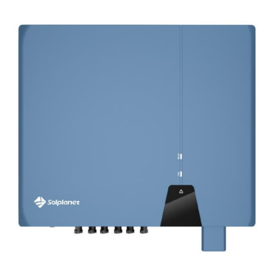
8 Display 8.1 Overview of the control panel The inverter is equipped with a display panel, which has 3 LED indicators. User Manual UM0016_ASW 25K-40K-LT-G3_EN_V02_0622... -
Page 51: Led Indicators
8.2 LED indicators The three LED indicators from top to bottom are: 1. SOLAR power indicator When the inverter is in the standby self-checking state, the white light flashes. Under normal grid-connected working state, the light is always on. In “Fault” mode, the light is off. 2. -
Page 52: Disconnecting The Inverter From Voltage Sources
9 Disconnecting the inverter from voltage sources Before performing any work on the inverter, disconnect it from all voltage sources as described in this section. Always adhere strictly to the given sequence. 1. Disconnect AC circuit breaker and secure against reconnection. - Page 53 screwdriver or an angled screwdriver (blade width: 3.5 mm) into one of the slide slots and pull the DC connectors out downwards. Do not pull on the cable. 5. Release and disconnect the AC connector. Unscrew the screws of the AC terminals, and then pull out the AC connector.
-
Page 54: Technical Data
10 Technical data 10.1 DC input data ASW25K-LT- ASW27K-LT- ASW30K-LT- Type Max. PV modules 37500 W 37800 W 39000 W ower(STC) Max. input voltage/ 1100V/630V Rated input voltage MPP voltage range 180~1000 V Full load MPP voltage 450 V - 850 V range Intitial feed-in voltage 160 V... - Page 55 ASW33K-LT- ASW36K-LT- ASW40K-LT- Type Max. PV modules 49500 W 50400 W 52000 W ower(STC) Max. input voltage/ 1100V/630V Rated input voltage MPP voltage range 180~1000 V Full load MPP voltage 450 V - 850 V range Intitial feed-in voltage 160 V Min input voltage 200V Max.
-
Page 56: Ac Output Data
3. The full-load MPP voltage range of the inverter is the value measured under the rated AC voltage. If you have any questions, please consult local service personnel. 10.2 AC output data ASW25K- ASW27K- ASW30K- Type LT-G3 LT-G3 LT-G3 Rated output power 25000W 27000W 30000W... - Page 57 Standby power loss <12 W Overvoltage category in accordance with IEC60664-1 ASW33K- ASW36K- ASW40K- Type LT-G3 LT-G3 LT-G3 Rated output power 33000W 36000W 40000W Max. output apparent 36300VA 39600VA 44000VA power 3/N/PE ,230/400V Rated AC Voltage (1) AC voltage range 180V-305V/312V-528V Rated AC Frequency (2) 50Hz/60Hz...
- Page 58 Overvoltage category in accordance with IEC60664-1 1. The AC voltage range depends on the local safety standards and rules. 2. The AC frequency range depends on the local safety standards and rules. User Manual UM0016_ASW 25K-40K-LT-G3_EN_V02_0622...
-
Page 59: General Data
10.3 General data ASW25K- ASW27K- ASW30K- Type LT-G3 LT-G3 LT-G3 Net weight 29Kg Dimensions(L×W×D) 543×520×235mm Mounting environment Indoor and Outdoor Mounting recommendation Wall bracket Operating temperature range -25…+60℃ Max. permissible value for relative humidity ( non- 100% condensing ) Max. operating altitude above 3000m mean sea level Ingress protection... - Page 60 ASW33K- ASW36K- ASW40K- Type LT-G3 LT-G3 LT-G3 Net weight 30Kg Dimensions(L×W×D) 463X543X225mm Mounting environment Indoor and Outdoor Mounting recommendation Wall bracket Operating temperature range -25…+60℃ Max. permissible value for relative humidity ( non- 100% condensing ) Max. operating altitude above 3000m mean sea level Ingress protection...
-
Page 61: Safety Regulations
10.4 Safety regulations Type ASW LT-G3 Series inverter Internal overvoltage Integrated protection DC insulation Integrated monitoring DC injection Integrated Grid monitoring Integrated monitoring Residual current Integrated monitoring Islanding protection Integrated (Three-phase monitoring) ) EN61000-6-1 EMC immunity EN61000-6-2 EN61000-6-3 EMC emission... -
Page 62: Tools And Torque
10.5 Tools and torque Tools and torque required for installation and electrical connections. Tools, model Object Torque Torque screwdriver, Screws for wall bracket 3N.m SW10 screws Hexagon screwdriver Screws for AC terminal 2N.m Screw for second Torque screwdriver, PH2 protective grounding 2.5Nm Cross head connection... - Page 63 Wear ESD glove when ESD glove opening the inverter Wear safety goggle Safety goggle during drilling holes. Wear anti-dust Anti-dust respirator respirator during drilling holes. User Manual UM0016_ASW 25K-40K-LT-G3_EN_V02_0622...
-
Page 64: Troubleshooting
11 Troubleshooting When the PV system does not operate normally, we recommend the following solutions for quick troubleshooting. If an error occurs, the red LED will light up. There will have “Event Messages" display in the monitor tools. The corresponding corrective measures are as follows: Error Object... - Page 65 • Make sure the grounding connection of the inverter is reliable. •Make a visual inspection of all PV cables and modules. If this fault is still shown, contact the service. • Check the open-circuit voltages of the strings and make sure it is below the maximum DC input voltage of the inverter.
- Page 66 Presumable Check the DRED device communication or Fault operation. • Disconnect the inverter from the utility grid and the PV array and reconnect it after LED turn off. If this fault is still being displayed, contact the Permanent service. Fault Warning code Warning message PV1 input over voltage...
-
Page 67: Maintenance
12 Maintenance Normally, the inverter needs no maintenance or calibration. Regularly inspect the inverter and the cables for visible damage. Disconnect the inverter from all power sources before cleaning. Clean the housing, cover and display with a soft cloth. Ensure the heatsink at the rear of the inverter cover is not covered. -
Page 68: Recycling And Disposal
The entire EU Declaration of Conformity can be found at http:// www.solplanet.net. User Manual UM0016_ASW 25K-40K-LT-G3_EN_V02_0622... -
Page 69: Warranty
15 Warranty The factory warranty card is enclosed with the package, please keep well the factory warranty card. Warranty terms and conditions can be downloaded at http:// www.solplanet.net, if required. When the customer needs warranty service during the warranty period, the customer must provide a copy of the invoice, factory warranty card, and ensure the type label of the inverter is legible. - Page 70 AISWEI Technology (Shanghai) Co., Ltd. Hotline: +86 400 801 9996 (Mainland) +886 809 089 212 (Taiwan) Service email: service.china@aiswei-tech.com Web: https://solplanet.net/contact-us/ Add.: Room 905B, 757 Mengzi Road, Huangpu District, Shanghai,200023,China AISWEI Pty Ltd. Hotline: +61 390 988 673 Service email: service.au@aiswei-tech.com Add.: Level 40, 140 William Street, Melbourne VIC 3000,...
- Page 71 User Manual UM0016_ASW 25K-40K-LT-G3_EN_V02_0622...
Need help?
Do you have a question about the ASW LT-G3 Series and is the answer not in the manual?
Questions and answers