Solplanet ASW45K-LT-G3 User Manual
Pv grid-connected inverter
Hide thumbs
Also See for ASW45K-LT-G3:
- Quick installation manual (16 pages) ,
- User manual (92 pages) ,
- Quick installation manual (62 pages)
Table of Contents
Advertisement
Quick Links
Advertisement
Table of Contents

Related Manuals for Solplanet ASW45K-LT-G3


Summary of Contents for Solplanet ASW45K-LT-G3
-
Page 2: Table Of Contents
6.7 COM 3&4 - Connection of Ripple control receiver / NS protection(Optional) ............35 7 Commissioning ............................... 37 7.1 Inspection before commissioning ..........................37 7.2 Commissioning procedure ............................. 37 8 Solplanet app ................................. 38 8.1 Brief introduction ................................38 8.2 Download and install ..............................38 8.3 Create an account ................................38 8.4 Create a plant ................................. - Page 3 10 Technical data ................................ 58 10.1 AC/DC ..................................58 10.2 General data ................................59 10.3 Protective device ................................. 60 11 Troubleshooting ..............................61 12 Maintenance ................................63 12.1 Cleaning the contacts of the DC switch ........................63 12.2 Cleaning air inlet and outlet ............................63 12.3 Fan maintenance .................................
-
Page 4: General Information
You will find the latest version of this document and further information on the product in PDF format at www.solplanet.net. It is recommended that this document is stored in an appropriate location and be available at all times. -
Page 5: Safety Warning Symbols Guide
Safety warning symbols guide DANGER Indicates a hazardous situation which, if not avoided, will result in death or serious injury. WARNING Indicates a hazardous situation which, if not avoided, could result in death or serious injury. CAUTION Indicates a hazardous situation which, if not avoided, could result in minor or moderate injury. NOTE Indicates a situation which, if not avoided, can result in property damage. -
Page 6: Safety
standards and directives. Any other application may cause personal injury or damage to property. The product must only be used in countries for which it is approved by Solplanet and the grid operator. The type label must be permanently attached to the product and must be in a legible condition. - Page 7 DANGER Danger to life due to electric shock when touching live system components in case of a ground fault ! If a ground fault occurs, parts of the system may still be live. Touching live parts and cables results in death or lethal injuries due to electric shock.
-
Page 8: Symbols On The Label
Symbols on the label Beware of a danger zone This symbol indicates that the inverter must be additionally grounded if additional grounding or equipotential bonding is required at the installation site. Beware of high voltage and operating current The inverter operates at high voltage and current. Work on the inverter must only be carried out by skilled and authorized electricians. -
Page 9: Unpacking And Storage
3 Unpacking and storage Scope of delivery Check the scope of delivery for completeness and any visible external damage. Contact your supplier if the scope of delivery is incomplete or damaged. Name Quantity Inverter Mounting-bracket AC/COM cover DC connector WiFi stick Screw accessory AC insulation sheet Document package... -
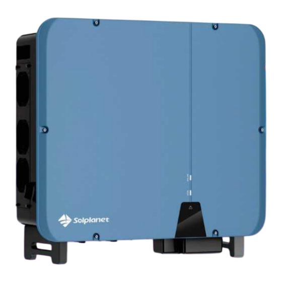
Page 10: Inverter Overview
4 Inverter overview Product description Name Description Side handles Used to hold and move the inverter. Holds the fans in place and allows for maintenance Fan assembly and replacement. Used to isolate the inverter from a DC input source DC switch e.g. -
Page 11: Dimensions
Dimensions LED indicator The LED indicator can indicate the operation state of the inverter. LED indicator LED state Description The white LED is solid ON when the product is operating Solid ON normally and feeding into the utility grid. SOLAR The white LED is blinking when the product is self-checking (White) Blinking... -
Page 12: Circuit Diagram
Supported grid types The grid types supported by Solplanet is TN-S, TN-C,TN-C-S, TT, as shown in the figure below: For the TT grid structure, the effective value of the voltage between the neutral wire and the ground wire must be less than 20V. - Page 13 The smart meter that can be used with inverter product must be approved by Solplanet. For more information about the smart meter, please contact the local service team.
- Page 14 This product complies with IEC 62109-2 clause 13.9 for earth fault alarm monitoring. If an Earth Fault Alarm occurs, the red color LED indicator will illuminate. At the same time, the error code 38 will be sent to the Solplanet Cloud. (This function is only available in Australia and New Zealand).
-
Page 15: Communication Overview
Communication overview The communication overview with a Wi-Fi stick: The communication overview with a LTE Cat-1 stick: One Wi-Fi stick or LTE CAT-1 stick can connect with up to five devices: UM0036_ASW45K-60K-LT-G3_EN_V03_0224... - Page 16 The communication overview with Ai-Logger for a large PV plant: UM0036_ASW45K-60K-LT-G3_EN_V03_0224...
-
Page 17: Mounting
5 Mounting Requirements for mounting DANGER Danger to life due to fire or explosion! Despite careful construction, electrical devices can cause fires. This can result in death or serious injury. Do not mount the product in areas containing highly flammable materials or gases. ... -
Page 18: Mounting
Maintain the recommended clearances to other inverters or objects. In case of multiple inverters, ensure the appropriate clearance between the inverters. The product should be mounted such that the LED indicators can be viewed without difficulty. The DC switch of the product must always be readily accessible. ... - Page 19 Step 1: Align the wall mounting bracket horizontally on the wall with the arrows pointing upwards. Mark the position of the drill holes. Set the wall mounting bracket aside and drill the marked holes with a diameter of 12 mm. The depth of the holes should be about 70 mm.
- Page 20 Step 4:Lift and place the inverter onto the mounting-bracket and ensure that the mounting flanges perfectly align with the mounting-bracket. Ensure that the four fixing points fit securely in the groove. Step 5:Secure the inverter to the mounting bracket with the screws provided. UM0036_ASW45K-60K-LT-G3_EN_V03_0224...
-
Page 21: Electrical Connection
6 Electrical connection Overview of the connection area *The figure shown here is for reference only. The actual product received may slightly differ! Name DC-switch DC input connectors Wi-Fi stick port Additional grounding terminal RS485 communication port AC terminal COM 3&4 - Connection of Ripple control receiver /NS protection device(Optional) COM 3&4 is standard on European machines only. -
Page 22: Connecting Additional Grounding
Connecting additional grounding The inverter is equipped with a grounding fault monitoring device. The grounding fault monitoring device will disconnect the inverter from utility grid when it detects there is no ground conductor connected. Hence the product does not require additional grounding or equipotential bonding when operating. -
Page 23: Ac Connection
Step 3:Apply paint to the grounding terminal to ensure corrosion resistance. AC connection 6.3.1 Requirements for the AC connection Cable Requirements The cable must be dimensioned in accordance with the local and national standards or for the dimensioning of cables. The requirements for the minimum wire are derived derive from these directives. - Page 24 Item Description a≤23mm 8.5mm≤b≤10.5mm Aluminium Cable Requirements If an aluminium cable is selected, use a copper to aluminium adapter terminal to avoid direct contact between the copper bar and the aluminium cable. Copper to Aluminium adapter terminal Aluminium cable Ensure that the selected adapter terminal makes direct contact with the copper bar. If there are any problems, contact the manufacturer of terminal.
- Page 25 This is necessary, for example, in an IT electrical system if there is no neutral conductor present and you intend to install the inverter between two line conductors. If you are uncertain about this, contact your grid operator or Solplanet. Safety in accordance with IEC 62109 when the ground fault monitoring is deactivated.
- Page 26 Step 3:Remove nut, take out the sealing ring, take out the plug, select the appropriate sealing ring according to the wire diameter, pass the cable through the waterproof connector on the AC/COM cover. Step 4:Strip the insulation from individual wires for L1 / L2 / L3 / N and PE (ground) so that the strand and insulation can be pressed into OT/DT terminal, reference 6.3.1.
- Page 27 Step 9:Install the AC insulation sheets onto the wiring terminals. NOTE Damage to the inverter due to incorrect wiring. If the phase line is connected to PE terminal, the inverter will not function properly. Please ensure the AC cables are connected to the correct terminals on the terminal block. ...
-
Page 28: Dc Connection
DC connection 6.4.1 6Requirements for the DC connection Requirements for the connection of PV modules per MPPT input All PV modules should be of the same type. All PV modules should be aligned and tilted identically. On the coldest day based on statistical records, the open-circuit voltage of the PV array must never exceed the ... - Page 29 Cable requirements: Item Description Value Cable type PV cable External diameter 5-8 mm Conductor cross-section 2.5-6 mm² Number of copper strands At least 7 The rated voltage ≥1100 V Procedure: Step 1: Strip 12 mm off the cable insulation. Step 2: Insert the stripped section into the DC connector. Push the clamping bracket down until it audibly snaps into place.
- Page 30 If the wire strands are not visible in the chamber, the cable is not correctly inserted and the connector must be reassembled. To do this, the cable must be removed from the connector. Release the clamping bracket by inserting a screwdriver (blade width: 3.5 mm) into the clamping bracket and pry the clamping bracket open.
- Page 31 Cable requirements: Item Description Value Cable type PV1-F,UL-ZKLA or USE2 External diameter 5-8 mm Conductor cross-section 2.5-6 mm² Number of copper strands At least 7 The rated voltage ≥1100 V Proceed as follows to assemble each DC connector. Step 1: Strip 12 mm off the cable insulation. Step 2:...
- Page 32 Step 4: Ensure that the cable is correctly positioned. 6.4.3 Connecting the PV array DANGER Danger to life due to high voltages in the inverter! When exposed to light, the PV modules generate high DC voltage which is present in the DC cables. Touching live DC cables may result in death or lethal injuries due to electric shock.
- Page 33 Step 3:Ensure that there is no ground fault in the PV array. Step 4:Check whether the DC connector has the correct polarity. If the DC connector is equipped with a DC cable having the wrong polarity, the DC connector must be reassembled. The DC cable must always have the same polarity as the DC connector.
- Page 34 Type 2 DC connector: Connect the assembled DC connectors to the inverter. Do not pull out the protective caps from unused DC input connectors. Check the positive and negative polarity of the PV strings, and connect the PV connectors to corresponding terminals only after ensuring polarity correctness.(The image below uses the type 2 connector as an example only.) Step 6:...
-
Page 35: Com 1 - Wi-Fi/Lan/4G Stick Connection
COM 1 - Wi-Fi/LAN/4G stick connection Step 1: Use the Wi-Fi stick included in the scope of delivery. Step 2: Remove the dust and waterproof cover of the Wi-Fi stick on the inverter and retain it. Step 3:Attach the Wi-Fi stick to the connection port in place and tighten it by hand with the nut on the Wi-Fi stick. Make sure the Wi-Fi stick is securely connected and the label on the Wi-Fi stick can be easily seen to allow for the scanning of the QR code during commissioning. -
Page 36: Com2 - Rs485 Connection
COM2 - RS485 connection NOTE Damage to the inverter due to electrostatic discharge. Internal components of the inverter can be irreparably damaged by electrostatic discharge. Ground yourself before touching any component. 6.6.1 Connection Procedure Step 1: Take out the relevant accessory from the package. Step 2:... - Page 37 Step 4: Strip the protection layer and insulation layer of the communication cable by the required, as described in the figure below. Step 5: Pass the cable through the gland on the AC/COM cover, and then guide the cable insert into the corresponding terminal.
-
Page 38: Com 3&4 - Connection Of Ripple Control Receiver / Ns Protection(Optional
If multiple inverters are connected in a daisy chain communication configuration, the the DIP switch settings are as follows: It is recommended to choose 3-core twisted wire to improve the anti-interference ability of S485 communication. The ground wire of the 3-core twisted wire can be connected to terminal G. COM 3&4 - Connection of Ripple control receiver / NS protection (Optional)... - Page 39 Step 1: RJ45 cable pin assignment as below, Strip the insulation from the wire and crimp it into the corresponding terminal. Step 2: Unscrew the communication port cover cap in the following arrow sequence and insert the network cable into the RJ45 communication client attached. Step 3:...
-
Page 40: Commissioning
Turn the DC switch of the inverter to the “ON” position. Set initial protection parameters via the Solplanet App. For details, please refer to “8.4 Create a plant”. Switch on the AC circuit breaker. If the irradiation and grid conditions meet the minimum thresholds, the inverter will operate normally. -
Page 41: Solplanet App
Procedure: Step 1: Open Solplanet App to enter the login screen, and tap “Don’t have an account” to enter the next screen. Step 2: The user groups “Business users” and “End user” need to be selected according to your identity, and tap “Next step”. - Page 42 Step 1 Step 2 Step 3 Step 4 Step 5 UM0036_ASW45K-60K-LT-G3_EN_V03_0224...
-
Page 43: Create A Plant
Create a plant Procedure: Step 1: Open Solplanet App to enter the login screen, enter the account name and password, and tap “Log in” to enter the next screen. Step 2: Tap the symbol “+” to enter the next screen, and tap “Create or Modify Plant”, then the camera of the smart device automatically turns on, and scan the QR code of the Wi-Fi stick to enter the next screen, tap “Create... - Page 44 Step 1 Step 2 UM0036_ASW45K-60K-LT-G3_EN_V03_0224...
- Page 45 Step 3 Step 4 Step 5 Step 6 UM0036_ASW45K-60K-LT-G3_EN_V03_0224...
- Page 46 Step 7 Step 8 Step 9 UM0036_ASW45K-60K-LT-G3_EN_V03_0224...
- Page 47 Step 10 Step 11 UM0036_ASW45K-60K-LT-G3_EN_V03_0224...
-
Page 48: Setting Parameters
8.5.1 Inverter configuration Solplanet’s products comply with local grid codes when leaving the factory. The grid code and the parameters according to the requirements of the installation site should still be checked and confirmed. Once configuration of the product is completed, the product will start operating automatically. - Page 49 8.5.2 Grid code settings For the Australia market, the inverter cannot be connected to the grid before the safety related area is set. Please select from Australia Region A/B/C to comply with AS/NZS 4777.2:2020, and contact your local electricity grid operator on which Region to select.
- Page 50 Step 1 Step 2 ○ ○ ○ ○ ○ ○ ○ ○ ○ ○ ○ Step 3 Step 4 UM0036_ASW45K-60K-LT-G3_EN_V03_0224...
- Page 51 Active power can increase at Active power can increase at a specific gradient once the a specific gradient once the voltage has returned to f voltage has returned to f reset reset Act. Power as a percentage of P , Linear Act.
- Page 52 Here, the Droop is different from the Droop S in section 3.7.2 of the standard EN 50549-1. ∆���� = × 100 The formula below should be used to manually configure the Droop S. (��������������������−����1)/�������� Droop S 8.5.2 Active power reduction at overvoltage P(U) There are five modes(Please refer to the following images)which can be chosen for this function and certain parameters can be configured according to the requirement of the local grid company.
- Page 53 ○ ○ ○ ○ ○ ○ ○ ○ ○ ○ ○ ○ Step 3 Step 4 Active power can increase at a Active power can increase at a specific gradient once the specific gradient once the voltage has returned to U voltage has returned to U reset reset...
- Page 54 Parameter Description Droop is defined as the active power as a percentage of P The active power will continuously move along the voltage characteristic curve Act. Power as a percentage of ○ in the voltage range of U to U start stop , Linear...
- Page 55 Step 1 Step 2 ○ ○ ○ ○ ○ Step 3 Step 4 Step 1: Tap “Reactive power settings” to enter to the next page. Step 2: Tap “Enable reactive power to choose the reactive power control mode and tap the left arrow to go back. Step 3:...
- Page 56 Table description Parameter Description ○ The active power as a percentage of P The displacement factor that is cosine of the phase angle between the ○ Cosφ fundamental components of the line to neutral point voltage and the respective current. ○...
- Page 57 Step 1: Tap “Reactive power settings” to enter to the next page. Step 2: Tap “Enable reactive power” to choose the reactive power control mode and tap the left arrow to go back. Step 3: Tap “Q(U) curve settings” to enter to the next page. Step 4:...
- Page 58 Table description Parameter Description ○ The voltage as a percentage of U ○ The reactive power as a percentage of P ○ Phase Choose the over-excited or under-excited. The lock-in active power value that enables the automatic reactive power Activating power as a delivery mode.
-
Page 59: Decommissioning The Product
9 Decommissioning the product Disconnecting the inverter from voltage sources Prior to performing any work on the product, always isolate it from all voltage sources as described in this section. Always adhere to the prescribed sequence. WARNING Danger to life due to electric shock from destruction of the measuring device due to overvoltage. Overvoltage can damage a measuring device and result in voltage being present in the enclosure of the measuring device. -
Page 60: Dismantling The Inverter
Step 6: Ensure that no voltage is present between the positive terminal and negative terminal at the DC inputs using a suitable measuring device. Step 7: Open the AC/COM cover junction box and use a multimeter to ensure that the AC wiring terminals isolated from an AC power source. -
Page 61: Technical Data
10 Technical data 10.1 AC/DC DC Input ASW60K-LT-G3 Type ASW45K-LT-G3 ASW50K-LT-G3 90000Wp Maximum power of PV array 67500Wp 75000Wp 1100V Maximum input voltage MPP voltage range 200-1000V 500-850V MPP voltage range at P Rated input voltage 630V 200V Minimum input voltage... -
Page 62: General Data
Adjustable displacement power factor ..0.8 inductive capacitive Feed-in phase Connection phase Overvoltage category in accordance with IEC 60664-1 Efficiency Maximum efficiency 98.6% European weighted efficiency 98.3% The voltage range meets the requirements of the corresponding national grid code. The frequency range meets the requirements of the corresponding national grid code. 10.2 General data General data ASW45K/50K/60K-LT-G3... -
Page 63: Protective Device
10.3 Protective device Protective devices ASW45K/50K/60K-LT-G3 Integrated DC reverse polarity protection Integrated DC isolator Ground fault monitoring Integrated AC short-circuit current capability Integrated All-pole sensitive residual current monitoring Integrated unit Active anti-islanding protection Integrated PV string current monitoring Integrated DC current injection monitoring Integrated Low voltage ride through Integrated... -
Page 64: Troubleshooting
11 Troubleshooting When the PV system does not operate normally, we recommend the following solutions for quick troubleshooting. If an error occurs, the red LED will turn solid ON. The error code can be read from the Solplanet APP. Error code... - Page 65 PIN7&PIN8, if connection is right, use multimeter measure RJ45's PIN7&PIN8 power voltage should lie in range of 8~24Vd.c.. If this fault occurs often, contact Solplanet service. Contact Solplanet service if you encounter errors not listed in the table above. UM0036_ASW45K-60K-LT-G3_EN_V03_0224...
-
Page 66: Maintenance
12 Maintenance 12.1 Cleaning the contacts of the DC switch DANGER High voltage of PV string may cause life danger! If the DC connector is disconnected while the PV inverter is working, an electric arc may occur causing electric shock and burns. - Page 67 Fans inside the inverter are used to cool the inverter during operation. If the fans do not operate normally, the inverter may not be cooled down and inverter efficiency may decrease. Therefore, it is necessary to clean the dirty fans and replace the broken fans in time.
-
Page 68: Recycling And Disposal
When the customer needs warranty service during the warranty period, the customer must provide a copy of the invoice, factory warranty card, and ensure the electrical label of the inverter is legible. If these conditions are not met, Solplanet has the right to refuse to provide with the relevant warranty service. -
Page 69: Contact
16 Contact EMEA Service email: service.EMEA@solplanet.net APAC Service email: service.APAC@solplanet.net LATAM Service email: service.LATAM@solplanet.net AISWEI Technology Co., Ltd Hotline: +86 400 801 9996 Add.: Room 904 - 905, No. 757 Mengzi Road, Huangpu District, Shanghai 200023 https://solplanet.net/contact-us/ UM0036_ASW45K-60K-LT-G3_EN_V03_0224... - Page 70 UM0036_ASW45K-60K-LT-G3_EN_V03_0224...
Need help?
Do you have a question about the ASW45K-LT-G3 and is the answer not in the manual?
Questions and answers