Sign In
Upload
Download
Table of Contents
Contents
Add to my manuals
Delete from my manuals
Share
URL of this page:
HTML Link:
Bookmark this page
Add
Manual will be automatically added to "My Manuals"
Print this page
×
Bookmark added
×
Added to my manuals
Manuals
Brands
Solplanet Manuals
Inverter
ASW LT Series
User manual
Solplanet ASW LT Series User Manual
Hide thumbs
Also See for ASW LT Series
:
User manual
(69 pages)
,
User manual
(76 pages)
1
Table Of Contents
2
3
4
5
6
7
8
9
10
11
12
13
14
15
16
17
18
19
20
21
22
23
24
25
26
27
28
29
30
31
32
33
34
35
36
37
38
39
40
41
42
43
44
45
46
47
48
49
50
51
52
53
54
55
56
57
58
59
60
61
62
63
64
65
66
page
of
66
Go
/
66
Contents
Table of Contents
Troubleshooting
Bookmarks
Table of Contents
Table of Contents
Notes on this Manual
General Notes
Area of Validity
Target Group
Symbols Used in this Manual
Safety
Intended Use
Important Safety Information
Symbols on the Type Label
Unpacking
Scope of Delivery
Check for Transport Damage
Mounting
Requirements for Mounting
Mounting the Inverter
Electrical Connection
Safety
Overview of the Connection Area
Electrical Connection Diagram with a Separate DC Isolator21
AC Connection
Conditions for the AC Connection
Grid Connection
Additional Grounding Connection
DC Connection
Requirements for the DC Connetion
Assembling the DC Connectors
Disassembling the DC Connectors
Connecting the PV Array
Conmunication Equipment Connection
Mounting the Wifi/Gprs Stick
The RS485 Connection
Communication
System Monitoring Via WIFI
System Monitoring Via RS485
Active Power Control with Smart Meter
Active Power Control Via Demand Response Enabling Device (DRED)
Communication with the Third Party Device
Earth Fault Alarm
Commissioning
Electrical Check
Mechanical Check
Safety Code Check
Start-Up
Display
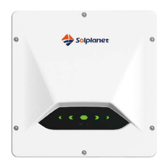
Overview of the Control Panel
LED Indicators
LED1~LED5 Green Power Indicator
LED6 Yellow Communication Indicator
LED7 Red Fault Indicator
Disconnecting the Inverter from Voltage Sources
Technical Data
DC Input Data
AC Output Data
General Data
Safety Regulations
Troubleshooting
Maintenance
Cleaning the Contacts of the DC-Switch
Cleaning the Heat Sink
Maintaining the Fan
Recycling and Disposal
EU Declaration of Conformity
Warranty
Contact
Advertisement
Quick Links
Download this manual
Table of
Contents
Previous
Page
Next
Page
1
2
3
4
5
Advertisement
Table of Contents
Need help?
Do you have a question about the ASW LT Series and is the answer not in the manual?
Ask a question
Questions and answers
Related Manuals for Solplanet ASW LT Series
Inverter Solplanet ASW LT Series User Manual
Three phase string inverters (76 pages)
Inverter Solplanet ASW LT Series User Manual
Three phase string inverters (69 pages)
Inverter Solplanet ASW LT-G2 Series User Manual
(69 pages)
Inverter Solplanet ASW LT-G3 Series User Manual
Three phase string inverters (71 pages)
Inverter Solplanet ASW LT-G3 Series User Manual
(87 pages)
Inverter Solplanet ASW LT-G2-A Series User Manual
(65 pages)
Inverter Solplanet ASW3K-LT-2 Pro Manual
(71 pages)
Inverter Solplanet ASW LT-G2 Pro Series User Manual
(62 pages)
Inverter Solplanet ASW8K-LT-G2 Pro Manual
Three phase inverters 8 to 20 kw (71 pages)
Inverter Solplanet ASW3000-T Quick Installation Manual
(37 pages)
Inverter Solplanet ASW30K-LT-G2 Quick Installation Manual
(71 pages)
Inverter Solplanet LT Series Quick Installation Manual
(102 pages)
Inverter Solplanet ASW75K-LT User Manual
(76 pages)
Inverter Solplanet ASW05kH-T2 User Manual
Three phase hybrid inverter (118 pages)
Inverter Solplanet ASW05kH-T2-DG User Manual
Three phase hybrid inverter (119 pages)
Inverter Solplanet ASW015K-TH Quick Installation Manual
(32 pages)
This manual is also suitable for:
Asw15k-lt
Asw20k-lt
Table of Contents
Print
Rename the bookmark
Delete bookmark?
Delete from my manuals?
Login
Sign In
OR
Sign in with Facebook
Sign in with Google
Upload manual
Upload from disk
Upload from URL


Need help?
Do you have a question about the ASW LT Series and is the answer not in the manual?
Questions and answers