Table of Contents
Advertisement
Quick Links
Advertisement
Table of Contents

Related Manuals for Samlex Europe PSC1600-12-60


Summary of Contents for Samlex Europe PSC1600-12-60
- Page 1 SINEWAVE INVERTER-CHARGER Sinewave inverter-charger Model No. PSC1600-12-60 PSC2000-12-80 PSC3000-12-120 PSC1800-24-35 PSC2500-24-50 PSC3500-24-70 Manual, Gebruiksaanwijzing, Benutzerhandbuch, Manuel Utilisateur, Manual Para Utilizador Please read this manual before operating your inverter-charger...
- Page 2 Europe BV. All rights reserved. No part of this document may be reproduced in any form or disclosed to third parties without the express written permission of Samlex Europe BV, Aris van Broekweg15, 1507 BA ZAANDAM, The Netherlands. Samlex Europe BV reserves the right...
-
Page 3: Table Of Contents
Powersine Combi TABLE OF CONTENTS 1. INTRODUCTION ........................4 2. DESCRIPTION .......................... 5 3. CONFIGURING THE POWERSINE COMBI ................6 General ........................6 Factory default parameter settings ................6 DIP switch settings overview ..................9 4. GENERAL OPERATION......................12 Operating the Powersine Combi ................12 Powersine Combi LED indicators and error modes ........... -
Page 4: Introduction
Powersine Combi 1. INTRODUCTION Thank you for purchasing a SAMLEX Powersine Combi inverter/charger combination. Please read this owner’s manual for information about using the product correctly and safely. Keep this owner’s manual and all other included documentation close to the product for future reference. -
Page 5: Description
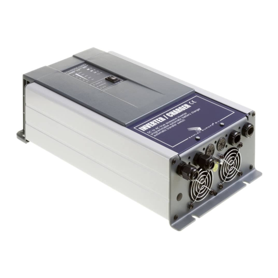
Powersine Combi 2. DESCRIPTION The Powersine Combi is an all-in-one combination of a DC to AC true sinewave inverter, an advanced multi-stage battery charger and a high speed AC transfer switch. All this is build into one compact, yet installer friendly enclosure. Besides these three main functions, there are several unique features offered as well. -
Page 6: Configuring The Powersine Combi
Powersine Combi 3. CONFIGURING THE POWERSINE COMBI General The Powersine Combi can be configured in two ways. Using the DIP switches located in the connection bay, a small selection of basic settings can be made. In most cases this will be sufficient to quickly setup the unit for typical applications. - Page 7 Powersine Combi Parameter Low Battery Protect Value Description Enables or disables low battery protection with user programmable shutdown, restart and delay values (standard respectively 10V, 12V and 5 seconds). Turning Low Battery Protect off, results in immediate inverter shutdown when the battery voltage is less than 8.0V. Configurable by DIP switch (DIP 3) and Dashboard Parameter...
- Page 8 Powersine Combi installer can either choose to deactivate the AC transfer switch, or keep it closed and allow it to exceed the AC input current limit value. This value can be set from 1.0A to 16.0A or 2.0A to 30.0A (depending on model) by Dashboard or the optional Universal Remote Control.
-
Page 9: Dip Switch Settings Overview
Powersine Combi chapters 3.3 and 5.1. Configurable by DIP switch (DIP 5 and 6) and Dashboard Parameter Charge current limit Value 100% Description This parameter sets the maximum charge current in percent. This value can be set from 10% to 100% by Dashboard or the optional Universal Remote Control. - Page 10 Powersine Combi ASB mode : ASB mode on Factory setting = OFF OFF : ASB mode off Battery type / Charge program 5 = OFF : Battery type = Flooded 6 = OFF Absorption voltage = 14.4V or 28.8V Float voltage = 13.5V or 27.0V 5 = ON : Battery type = GEL 6 = OFF Absorption voltage = 14.2V or 28.4V...
- Page 11 Powersine Combi Models : PSC2000-3500 only Reserved Factory setting = OFF Models : PSC2000-3500 only Bypass remote switch (Bypasses the remote switch connection when no remote switch is connected) : Remote switch connection terminals are bypassed OFF : remote switch connection terminals are open. A remote switch must be connected and switched ON Factory setting = ON in order to activate the Powersine Combi.
-
Page 12: General Operation
Powersine Combi 4. GENERAL OPERATION Operating the Powersine Combi The main switch on the Powersine Combi has three positions : On, Off and Charger only (see image in chapter 4.2). When switched to On, the Powersine Combi will perform all tasks automatically. It will power up in inverter mode, supplying power to the connected load. - Page 13 Powersine Combi The frontpanel can be divided into four sections : 1. Dual function level bar. Indicates the percentage of delivered output power in inverter mode (turns red if more than nominal output power is being delivered to the load). In charger mode, this level bar indicates the percentage of delivered charging current.
-
Page 14: Error Indications
Powersine Combi 3. Charge status bar. Gives a rough indication of the charging progress, see below : LED 3a : 100% full (ready) LED 3b : 80% full LED 3c : 50% full LED 3d : empty 4. Power on, off, charger only switch. See chapter 4.1 for more explanations. 4.2.1. -
Page 15: Trigger Input
Powersine Combi Relay 2 on the PSC2000-3500 models will be activated only after the AC supply has become available. In case of battery operation, Relay 2 will deactivate immediately. This can be used to switch less critical AC loads (i.e. electric boiler, aircon) on and off that are allowed to be supplied by the mains or generator only. -
Page 16: Charger Operation
Powersine Combi 5. CHARGER OPERATION Charge programs All standard selectable charge programs (using DIP switches 5 and 6), perform a four stage IUoUoP charging process comprising of a “Bulk”, an “Absorption”, a “Float” and a “Pulse” stage. The image below visualizes the four stage charging process : In the Bulk stage, the charger delivers full output current and typically returns approximately 80% of charge back into the battery once the absorption voltage is reached. -
Page 17: Equalizing A Flooded Battery
Powersine Combi declining battery voltage. At a certain battery voltage level, the charger jumps back to the Bulk stage and will finalize a complete charging process again, once the battery load consumption has dropped below the charger's maximum output current level. The fourth stage called “Pulse”, will perform a short refresh charge of approximately 1 hour each 7 days while the charger operates in the Float stage. - Page 18 Powersine Combi battery damage. Therefore, equalizing a battery is always a process that must continuously be supervised by the user. Since equalization is only allowed for flooded (wet-) lead acid batteries, the Powersine Combi will only allow this function to be available when the “Flooded” charging program is selected (see chapter 3.3).
-
Page 19: Troubleshooting Guideline
Powersine Combi 6. TROUBLESHOOTING GUIDELINE Please see the table below if you experience any problems with the Powersine Combi and/or the installation. Problem Possible cause Remedy Powersine Combi is not Main switch in Off (0) Push the power switch in the working at all. - Page 20 Powersine Combi Additional battery loads are Turn-off or disconnect all consuming too much current battery loads. during charging. Charge current is too low. High ambient temperature. Try to lower the ambient temperature around the Powersine Combi. Charger is operating in the Do nothing.
- Page 21 Powersine Combi Connected AC output load Try to power-up connected causes a too large inrush equipment successively, and current. not simultaneously. Otherwise stop using the connected load, it's not suitable to power it with this inverter. Mode indicator LEDs The Powersine Combi has Reduce the AC output load in ‘inverter on’...
- Page 22 Powersine Combi Mode indicator LED ‘charger Charge program error. User has selected an empty on’ blinks five times. or invalid charge program (‘custom’ charge program is empty from factory). Advanced user made charge program contains ‘go-to error’ condition, for example when a charge stage takes too much time.
-
Page 23: Technical Specifications
Powersine Combi 7. TECHNICAL SPECIFICATIONS Parameter PSC1600-12-60 PSC1800-24-35 Inverter stage Output power Pnom 1300W 1400W P10minutes 1600W 1800W Psurge 2500W 3000W Output voltage / frequency 230Vac ± 2% / 50Hz ± 0.05% Output waveform True sinewave (THD < 5% @ Pnom) Input voltage (±... - Page 24 Powersine Combi Parameter PSC2000-12-80 PSC2500-24-50 Inverter stage Output power Pnom 1800W 2000W P10minutes 2100W 2500W Psurge 4000W 5500W Output voltage / frequency 230Vac ± 2% / 50Hz ± 0.05% Output waveform True sinewave (THD < 5% @ Pnom) Input voltage (± 3% tolerance): Nominal Range 10.5 –...
- Page 25 Powersine Combi Parameter PSC3000-12-120 PSC3500-24-70 Inverter stage Output power Pnom 2600W 2800W P10minutes 3200W 3800W Psurge 5000W 6500W Output voltage / frequency 230Vac ± 2% / 50Hz ± 0.05% Output waveform True sinewave (THD < 5% @ Pnom) Input voltage (± 3% tolerance): Nominal Range 10.5 –...
-
Page 26: Warranty Conditions
Powersine Combi 8. WARRANTY CONDITIONS Samlex Europe (SAMLEX) warrants this product to be free from defects in workmanship or materials for 24 months from the date of purchase. During this period SAMLEX will repair the defective product free of charge. SAMLEX is not responsible for any costs of the transport of this product. -
Page 27: Declaration Of Conformity
Declares that the following products : PRODUCT TYPE : Professional inverter / charger combination MODELS : PSC1600-12-60, PSC1800-24-35, PSC2000-12-80, PSC2500-24-50, PSC3000-12-120, PSC3500-24-70 Conforms to the requirements of the following Directives of the European Union : EMC Directive 2004/108/EC The above product is in conformity with the following harmonized standards :... - Page 28 www.samlex.com www.samlex-solar.com...
Need help?
Do you have a question about the PSC1600-12-60 and is the answer not in the manual?
Questions and answers