
Related Manuals for Samlex Europe ELOGIC


Summary of Contents for Samlex Europe ELOGIC
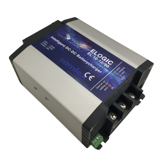
- Page 1 INTELLIGENT DC-DC BATTERYCHARGER ELOGIC Model No. EL 12-12/50 (12V/50A) EL 12-24/30 (24V/30A) Owners Manual Please read this manual before operating your Elogic Batterycharger...
- Page 3 Notice of Copyright EL 30-50 Elogic DC-DC battery charger owner’s manual © 2020 SAMLEX EUROPE BV. All rights reserved. No part of this document may be reproduced in any form or disclosed third parties without the express written permission of SAMLEX EUROPE BV, Aris van Broekweg 15, 1507 BA, Zaandam, The Netherlands.
-
Page 4: Table Of Contents
TABLE OF CONTENTS 1. INTRODUCTION ........................5 Intended product use ..................... 5 Important safety information ..................5 2. INSTALLATION ........................... 7 Unpacking ........................7 Mounting ........................7 Wiring details ........................8 3. GENERAL FUNCTIONALITY ...................... 14 The charging process ....................14 Charger operation using the main On/Off control input .......... -
Page 5: Introduction
Intended product use The Elogic DC to DC battery chargers are primarily intended to charge an auxiliary or service battery from a vehicle starter battery. The input battery voltage can be above, below or equal to the output battery voltage. - Page 6 WARNING FAILURE TO FOLLOW THESE INSTRUCTIONS CAN RESULT IN DEATH OR SERIOUS INJURY: 1. When working with electrical equipment or lead acid batteries, have someone nearby in case of an emergency. 2. Study and follow all the battery manufacturer’s specifc precautions when installing, using and servicing the battery connected to the charger.
-
Page 7: Installation
2. INSTALLATION Unpacking The charger package should contain the following items : ― Battery charger ― 3x rubber cable grommets ― Battery temperature sensor (3m) ― Owner’s manual ― 3x M6 crimp terminals CAUTION After unpacking, check if the product shows any mechanical damage. Never use the product when the enclosure shows any visual damage caused by harsh handling, or when it has been dropped accidentally. -
Page 8: Wiring Details
6. Use the base of the charger as a mounting template to mark the positions of the fixing screws. CAUTION Keep a clear space of at least 10 cm around this product for cooling purposes! Wiring details WARNING For user safety during installation, please make sure that the output of the supplying source is switched off (temporary remove fuses from the fuseholders) and that no consumers are connected to the batteries. - Page 9 Before connecting the main DC cables, make sure to slide the included rubber grommets over these cables like shown in the next image. When the DC cables are connected to the charger, the rubber grommets can be slid towards the charger’s front panel until the screw connections are completely covered. Please see the image below for further wiring details.
- Page 10 CAUTION Double check for correct polarity, before connecting the battery cables to the battery! Wrong polarity will blow an internal fuse and the charger must be returned for service. Always keep positive and negative cables close to each other to minimize electromagnetic fields. ➀...
- Page 11 ➂ Please see the image below for the control wire connection locations. Connection 1 is the main On/Off control input and can only be used when DIP switch 4 is set to off. This input can be used to enable or disable the charger and is ‘active high’. When a voltage higher than 2V is applied to this input, the charger turns on.
- Page 12 ➃ DIP switch settings DIP switch 1 and 2 are used select the desired charge program for the connected output battery. Please see the table below: DIP1 DIP2 Battery type / Charge program ¹⁾ ²⁾ Flooded (default setting) Bulk/Abs voltage = 14.4V (28.8V) Float voltage = 13.5V (27.0V) ¹⁾...
- Page 13 ➄ The remaining connection options are shown below Battery temperature sensor for temperature compensated charging The optional QuickLink communication Kits allow the charger to be programmed and monitored using the Samlex Dashboard software on PC (via USB or RS232) or the Dashboard Mobile app on iOS and Android platforms (via Bluetooth).
-
Page 14: General Functionality
3. GENERAL FUNCTIONALITY The charging process All selectable charge programs, perform a three stage IUoUo charging process comprising of a “Bulk” , an “Absorption”, and a “Float” stage. The image below visualizes the three stage charging process: When charger is turned on, it will start in the Bulk stage. In this stage the charger delivers full output current and typically returns approximately 80% of charge back into the battery once the absorption voltage is reached. -
Page 15: Charger Operation Without Using The Main On/Off Control Input
Additionally, this condition must also be met for a preset amount of time. Please see the table below showing all factory default voltage and time delay values that are stored inside the Elogic DC charger:... -
Page 16: Led Indicators
LED indicators The Elogic DC units are equipped with individual LEDs for the input- and the output side. Please see the image below for the location of these LEDs: The table below explains all available LED conditions: Status Explanation Input LED... -
Page 17: Troubleshooting Guideline
4. TROUBLESHOOTING GUIDELINE Please see the table below if you experience any problems with the Elogic DC battery charger and/or the installation. Problem Possible cause Remedy Elogic DC is not working No input voltage. Check wiring and input fuse. at all. -
Page 18: Technical Specifications
If none of the above remedies will help solving the problem you encounter, it’s best to contact your local Samlex distributor for further help and/or possible repair of your Elogic DC unit. Do not disassemble the charger yourselves as this will void your warranty. - Page 19 Parameter EL 12-12/50 EL 12-24/50 Cooling Variable speed fan Communication port Samlex QuickLink Temperature sensor port Yes (sensor included) Engine run / activate input port Yes (> 2.0Vdc = Active and < 1.0Vdc = Inactive) BMS input port Yes (> 3.0Vdc = Standby and < 1.0Vdc = Active) Status output port Yes (open drain, 32Vdc / 150mA max, five assignable status types)
-
Page 20: Warranty Conditions
6. WARRANTY CONDITIONS Samlex Europe (Samlex) warrants this product to be free from defects in workmanship or materials for 24 months from the date of purchase. During this period Samlex will repair the defective product free of charge. Samlex is not responsible for any costs of the transport of this product. -
Page 21: Declaration Of Conformity
Aris van Broekweg 15 1507 BA Zaandam. The Netherlands Declares that the following products: PRODUCT TYPE Elogic DC to DC battery charger MODELS EL 12-12/50, EL 12-24/30 Conforms to the requirements of the following Directives of the European Union: EMC Directive 2014/30/EU... - Page 22 www.samlex.com www.samlex-solar.com...
Need help?
Do you have a question about the ELOGIC and is the answer not in the manual?
Questions and answers