Table of Contents
Advertisement
Quick Links
Advertisement
Table of Contents

Subscribe to Our Youtube Channel
Related Manuals for GKD 1H Series


Summary of Contents for GKD 1H Series
- Page 1 HEIGHT LIMITER INSTALLATION MANUAL COPYRIGHT NOTICE Intended audience: This document contains sensitive information. It may not be shared with other parties without the express written permission of GKD Technologies Ltd. M1000005 V1.5 - 11/2021...
-
Page 2: Table Of Contents
CONTENTS Page OVERVIEW 2 MAIN SYSTEM COMPONENTS Display Angle Sensor 3 SERIES 1-H INDICATORS AND CONTROLS 4 SYSTEM LAYOUT 5 DISPLAY INSTALLATION Electrical Connections Relay Outputs CAN Bus Connection 6 ANGLE SENSOR INSTALLATION GRAVITY V angle sensor option Terminating Resistor 7 MOTION CUT SOLENOID VALVE INSTALLATION Operating Principle –... - Page 3 8 CALIBRATION Horizontal Position Setting 9 SETTING A HEIGHT LIMIT 10 FAULT FINDING 10.1 Fault LED 10.2 Angle sensor, no LED 10.3 Angle sensor, red LED 10.4 No motion cut or external alarm 10.5 Motion cut not working www.gkdtechnologies.com M1000005 V1.5 - 11/2021...
-
Page 4: Overview
OVERVIEW The Series 1-H is a height limiting system intended for use on excavators, loaders, teletrucks or similar type machines. The system monitors the angle of the primary boom or arm and compares this angle against a previously stored limit, set by the machine operator. When the boom is lifted to the point where the boom angle approaches the stored “limit”... -
Page 5: Series 1-H Indicators And Controls
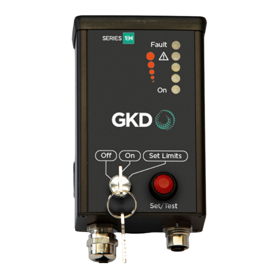
3 SERIES 1-H INDICATORS AND CONTROLS Indicator LEDs in ACTIVE mode: (see detailed notes in sections below) Indicates fault with the Series 1-H system or configuration Fault Indicates System has reached 95% of maximum height limit. Indicates System has reached 75% of maximum height limit. -
Page 6: System Layout
4 SYSTEM LAYOUT Gravity V Angle Sensor Connect to machine ignition via a 5A Fuse RED: = +V IN BLUE = Relay Common BLACK = 0V (Chassis) YELLOW = Relay N/O GREEN = Relay N/C Motion Cut Solenoid External Sounder (optional) www.gkdtechnologies.com M1000005 V1.5 - 11/2021... -
Page 7: Display Installation
5 DISPLAY INSTALLATION The display should be installed in the machine cab at the operator station, in a position where it can easily be seen and accessed by the operator. Normally this will be on the operator’s right side, near the front of the cab. The display is mounted using a RAM bracket, which will enable the display to be positioned facing the operator. -
Page 8: Angle Sensor Installation
6 ANGLE SENSOR INSTALLATION GRAVITY V angle sensor option The GRAVITY V angle sensor is installed onto the boom to be monitored. Identify a position for the sensor on the side of the boom, where it is not likely to be damaged by machine components or to catch moving cables or hydraulic hoses as machine components articulate. -
Page 9: Terminating Resistor
Once a suitable position has been identified, remove a small area of paint from the install site at each end of the angle sensor mounting shoe, and weld the mounting shoe to the arm using the V shaped cutout at each end of the mounting shoe. Weld Weld Treat the area of the weld with anti rust compound and paint to prevent rust forming. -
Page 10: Motion Cut Solenoid Valve Installation
7 MOTION CUT SOLENOID VALVE INSTALLATION If motion cut on height limit is required, a three port solenoid valve should be installed in the low pressure Pilot hydraulic line between the machine control lever and the high pressure valve block. Identify the pilot line controlling the boom lift hydraulic function. -
Page 11: Calibration
8 CALIBRATION Once installation has been completed, set the Series 1-H display key switch to “On” mode and switch on the ignition, causing the Series 1-H system to power up. At power up, all 5 LEDs will come on and the internal sounder bleeps as a self-test. The LEDs will then go off in turn. -
Page 12: Setting A Height Limit
9 SETTING A HEIGHT LIMIT To set a height limit, turn the key switch to the “SET” position and raise the boom of the machine to the desired maximum height position. Note: the configuration of the machine equipment will depend on how it is positioned when setting a height limit. -
Page 13: Fault Finding
10 FAULT FINDING 10.1 Fault LED If the “Fault” LED is lit, a connection error is present between the Series 1-H display and the angle sensor. Check the CAN bus cable between the display and the angle sensor for damage or incorrect connection. NOTE: On first switch on, before the Horizontal boom position has been learned, it is normal for the fault light to flash. - Page 14 INSTALLER NOTES www.gkdtechnologies.com M1000005 V1.5 - 11/2021...
- Page 15 www.gkdtechnologies.com M1000005 V1.5 - 11/2021...
- Page 16 DISCLAIMER Incorrect installation of any part and or incomplete calibration will affect the correct operation of the Series 1-H. If in doubt contact GKD Technologies. GKD Technologies reserve the right to change these instructions in line with the policy of continuous improvement.
Need help?
Do you have a question about the 1H Series and is the answer not in the manual?
Questions and answers