Advertisement
Quick Links
Advertisement

Related Manuals for Hella 2RL 014.567 Series


Summary of Contents for Hella 2RL 014.567 Series
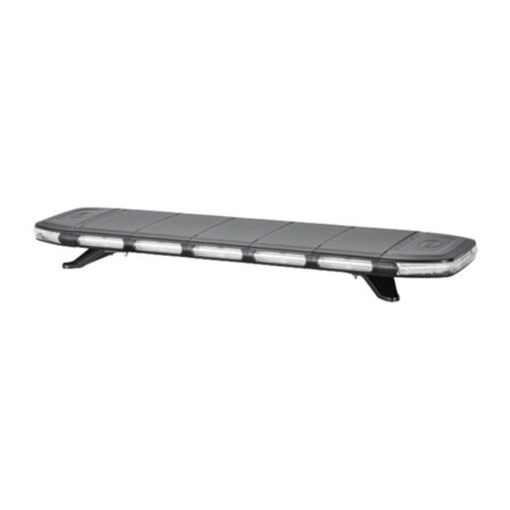
- Page 1 MONTAGEANLEITUNG MODULAR LIGHTBAR INSTALLATION INSTRUCTION MODULAR LIGHTBAR...
-
Page 2: Table Of Contents
• Only use original spare parts or spare parts approved by HELLA. • If you have any questions or problems with the installation, please contact HELLA Customer Services, a wholesaler or your garage. • Further information is available on our website (www.hella.com/techworld) -
Page 3: Zeichenerklärung
Zeichenerklärung Explanation of symbols Richtig Falsch Positionspfeil Bewegungspfeil Correct Incorrect Location/Position Arrow Movement Arrow Achtung Abklemmen Verbinden Siehe Warning Disconnect Connect Look/See Benötigte Montagewerkzeuge Necessary installation tools Ø11 mm SW 10 Lieferumfang Scope of delivery seitliches Arbeitslicht Side Light Modules Beschreibung “Typgenehmigung”... - Page 4 Lieferumfang Scope of delivery Bedieneinheit, abhängig von der Konfiguration Control unit, depending on the configuration LEFT LEFT ON/OFF NEXT ON/OFF NEXT ALLEY ALLEY TAKE TAKE BACK BACK DOWN DOWN RIGHT RIGHT NIGHT NIGHT RESET RESET ALLEY WARNING LIGHTBAR ALLEY WARNING LIGHTBAR Bedieneinheit, kabelgebunden Bedieneinheit, kabellos* Schalter...
- Page 5 Montage Mounting 7 - 8 457.2 457.2 ±2.5 mm ±2.5 mm 609.6 609.6 ±2.5 mm ±2.5 mm ±2.5 mm ±2.5 mm 914.4 ±2.5 mm 1066.8 ±2.5 mm 1219.2 ±2.5 mm 1371.6 ±2.5 mm 1524 ±2.5 mm...
- Page 6 Montage Mounting Die Positionierung der Stiftschrauben is so zu wählen, dass eine stabile Montage des Dachbalkens auf dem Fahrzeugdach gewährleistet ist! The positioning of the studs is to be chosen so that a stable installation of the roof beam on the vehicle roof is guaranteed! Ø11 mm Ø11 mm...
- Page 7 Montage Mounting...
- Page 8 Montage Mounting max. 2,5 Nm Ø11 mm Ø11 mm Bei der Durchführung des Kabelbaums durch das Dach, ist auf eine Fachgerechte Abdichtung zu achten! When running the cable harness through the roof, ensure that it is properly sealed!
-
Page 9: Electrical Connection
Elektrischer Anschluss Electrical connection Weiß White Orange Orange Schwarz Black Braun Brown VI/BR Violett/Braun Purple/Brown Gelb Yellow Grün Green RT/WS Rot/Weiß Red/White Grau Grey Blau Blue GRGN Grau/grün Gray/green Dachbalkentyp Warnfarbe Mittelmodul externe Sicherung externe Sicherung Beschreibung Lightbar Type Warning Color Center module external fuse external fuse... - Page 10 Elektrischer Anschluss Electrical connection Verkabelung Schalter Wiring Simple switch Farbe Funktion Verbindung Colour Function Connection “+” Dachbalken “+” “+” Connect to lightbar “+” “-” Dachbalken “-” und Fahrzeugbatterie “-” Connect to lightbar “-” “-” & vehicle battery “-” Blitzmuster Dachbalkenseitig mit GE verbinden (Blitzmuster) Pattern Connect to GE (fl...
- Page 11 Elektrischer Anschluss Electrical connection Verkabelung Modular Lightbar Wiring Modular lightbar Farbe Funktion Colour Function Dachbalken “+” Lightbar “+” Fahrzeugbatterie “-” Vehicle battery “-” Blitzmuster Flash pattern Bremslicht RT/WS Stop light Schlusslicht/Beleuchtetes Logo VI/BR Tail light/illuminated Logo Fahrtrichtungsanzeiger links GR/GN Direction indicator le Fahrtrichtungsanzeiger rechts Direction indicator right Bedieneinheit “+”...
- Page 12 Elektrischer Anschluss Electrical connection Verkabelung Modular Lightbar Wiring Modular lightbar Farbe Funktion Colour Function Dachbalken “+” Lightbar “+” Fahrzeugbatterie “-” Vehicle battery “-” Blitzmuster Flash pattern Bremslicht RT/WS Stop Light Schlusslicht / beleuchtetes Logo VI/BR Tail light / illuminated logo Fahrtrichtungsanzeiger links GR/GN Direction indicator le...
-
Page 13: Technical Data
Conformity according to CE, REACh, RoHS, ELV Die Anwendung des Produkts liegt in der Application of the prodcuct is user responisibility. Verantwortung des Benutzers. Technical conditions according to Hella HN 67101 Technische Bedingungen nach Hella HN 67101 Emergency car (10.1) •... - Page 14 Funktionen der Bedieneinheit 1. Funktionen des modularen Dachbalkens Generelles Der Dachbalken ist als modulares System aufgebaut und kann flexibel mit unterschiedlichen Mittelmodulen bestückt werden. Wird die Bestückung der Mittelmodule geändert (z. B. nach einem Reparaturaustausch oder einer Funktionserweiterung), muss die Elektronik des Dachbalkens neu gestartet werden, um die neuen Module ansteuern zu können. 1.1.1 Neustart des Dachbalkens Bei Verwendung des Schalters: Drücken und halten Sie die “Pattern”...
- Page 15 Funktionen der Bedieneinheit Display der Bedieneinheit (kabelgebunden und kabellos): • „E“ (Error = Fehler): Zeigt dem Nutzer an, dass ein Fehler am Dachbalken vorliegt. • „b“ (break = getrennt): Zeigt an, dass der Dachbalken nicht mit der Bedieneinheit verbunden ist. •...
- Page 16 Funktionen der Bedieneinheit 2.3 Koppeln der kabelgebundenen Steuerbox: Alle Dachbalkens werden mit bereits gekoppelter kabelgebundener Steuerbox geliefert. Falls eine neue Kupplung erforderlich ist: 2.3.1 Drücken und halten Sie die „ON/OFF“-Taste, um in den Kupplungsmodus zu gelangen, eine Kupplungszählung beginnt. 2.3.2 Nach Ablauf des Kupplungszählung erscheint „D“ auf dem Bildschirm, was bedeutet, dass die Kopplung erfolgt ist. Hinweis: Der Kopplungsprozess der Bedieneinheit lernt automatisch alle aktuellen Blitzmuster des Dachbalkens.
-
Page 17: Control Box Functions
Control box functions 1. Functions of the modular lightbar General The roof beam is designed as a modular system and can be flexibly equipped with different middle modules. If the equipment of the middle modules is changed (e.g. after a repair replacement or a function expansion), the electronics of the lightbar must be restarted in order to be able to control the new modules. - Page 18 Control box functions Control box display: • “E” (Error): Indicates to the user that there is an error on the roof beam. • “B” (break = separated): Indicates that the lightbar is not connected to the control unit. • “L”: If the control unit is normally connected to the light, an “L” (link) is displayed on the control unit. •...
- Page 19 Control box functions 2.3 Coupling the wired control box: All lightbars are supplied with a wired control box already connected. If a new coupling is required: 2.3.1 Press and hold the “ON / OFF” button to enter the coupling mode, a coupling countdown begins. 2.3.2 When the countdown has finished, “D”...
- Page 20 Beleuchtungsanlage auf einwandfreie Funktion hin prüfen Check that the lighting system is working perfectly...
- Page 21 HELLA GmbH & Co. KGaA Rixbecker Straße 75 59552 Lippstadt /Germany www.hella.com © HELLA GmbH & Co. KGaA, Lippstadt 460 838-40 /11.21...
Need help?
Do you have a question about the 2RL 014.567 Series and is the answer not in the manual?
Questions and answers