Infineon XENSIV CSK BGT60TR13C User Manual
Hide thumbs
Also See for XENSIV CSK BGT60TR13C:
- Installation manual (27 pages) ,
- Getting started manual (25 pages) ,
- Manual (21 pages)
Advertisement
Quick Links
UM_2205_PL32_2205_105330
User Guide for XENSIV™ KIT CSK BGT60TR13C
About this document
Scope and purpose
This document is a user guide for the XENSIV™ KIT CSK BGT60TR13C, provided as part of the connected sensor
kit (CSK) offering.
Intended audience
Customers interested in using CYSBSYSKIT-DEV-01 in combination with the XENSIV™ BGT60TR13C radar sensor
or the XENSIV™ DPS368 barometric pressure sensor to build their own IoT solution for various consumer
applications.
Please read the Important Notice and Warnings at the end of this document
www.infineon.com
page 1 of 59
2022-23-05
Advertisement

Related Manuals for Infineon XENSIV CSK BGT60TR13C


Summary of Contents for Infineon XENSIV CSK BGT60TR13C
- Page 1 Customers interested in using CYSBSYSKIT-DEV-01 in combination with the XENSIV™ BGT60TR13C radar sensor or the XENSIV™ DPS368 barometric pressure sensor to build their own IoT solution for various consumer applications. Please read the Important Notice and Warnings at the end of this document www.infineon.com page 1 of 59 2022-23-05...
- Page 2 User Guide for XENSIV™ KIT CSK BGT60TR13C Important notice Table of contents About this document ........................1 Table of contents ..........................2 Important notice ........................4 Introduction .......................... 5 Kit content ............................... 5 CYSBSYSKIT-DEV-01 ..........................6 2.2.1 CYSBSYSKIT-DEV-01 main components .................... 6 XENSIV™...
- Page 3 User Guide for XENSIV™ KIT CSK BGT60TR13C Important notice 7.1.7 Expansion headers ........................... 44 7.1.8 QSPI ..............................44 7.1.9 LED ..............................45 7.1.10 User button ............................45 7.1.11 ECO ..............................45 7.1.12 10-pin SWD/JTAG programming header ..................46 7.1.13 KitProg3: on-board programmer/debugger ................... 46 7.1.14 Programming and debugging ......................
- Page 4 • The evaluation unit is intended to be used for development, TESTING and EVALUATION PURPOSES ONLY and is not considered by Infineon to be a finished end product fit for general consumer use. • The evaluation unit (not being an end product) is not intended to be complete in various product aspects such as required design, marketing, manufacturing, product safety, security and environmental measures.
- Page 5 User Guide for XENSIV™ KIT CSK BGT60TR13C Table of contents Introduction The XENSIV™ KIT CSK BGT60TR13C supports customers in testing sensor-driven IoT products and radar use cases as well as in prototyping. It offers a real-time sensor evaluation with custom configurations and cloud- based radar-based solution output visualization.
- Page 6 The user signs up with the Infineon® Rapid IoT connect cloud platform and registers the Rapid IoT connect developer kit with the unique serial number printed on it. The user chooses an application for evaluation on the Rapid IoT connect developer kit.
- Page 7 User Guide for XENSIV™ KIT CSK BGT60TR13C Table of contents A user LED, a user button, and a reset button • Battery connector, charging IC, and charging indicator LED • One KitProg3 mode button, one KitProg3 status LED, and one KitProg3 power LED •...
- Page 8 User Guide for XENSIV™ KIT CSK BGT60TR13C Table of contents sensitivity allows detection of movements down to sub-millimeter. Via the very commonly used SPI (Serial Peripheral Interface) the host MCU first configures the sensor, then reads the acquired sensor data, and finally performs the application-specific signal processing steps.
- Page 9 The CYSBSYSKIT-DEV-01 rapid IoT connect developer kit serves as the compute and connect part of the CSK. Infineon sensor wing boards, such as the XENSIV™ BGT60TR13C radar wing, sense the environment. The wing board has Adafruit feather-compatible connectors to be stacked individually or combined with other CSK- compatible wing boards on the rapid IoT connect developer kit.
- Page 10 User Guide for XENSIV™ KIT CSK BGT60TR13C Table of contents Figure 5 XENSIV™ BGT60TR13C radar wing block diagram A system block diagram showing the shield connected to the CSK rapid IoT baseboard is depicted in Figure 6. The interface from the shield to the rapid IoT baseboard includes I C, digital signals, analog signals and power lines.
- Page 11 User Guide for XENSIV™ KIT CSK BGT60TR13C Table of contents Getting started This guide will help you to get acquainted with the XENSIV™ KIT CSK BGT60TR13C: • Chapter Quick IoT Experience demonstrates how to read sensors and connect to the Rapid IoT connect cloud platform in less the 10 minutes •...
- Page 12 User Guide for XENSIV™ KIT CSK BGT60TR13C Table of contents Abbreviations Table 1 Abbreviations used in this document Abbreviation Description Board support package Connected sensor kit GPIO General-purpose input/output Hardware Inter-integrated circuit Internet of Things Light-emitting diode Photoacoustic spectroscopy Printed circuit board PSoC Programmable system-on-chip Serial peripheral interface...
- Page 13 Table of contents Quick IoT Experience Signup and login: Create an account with the Infineon® Rapid IoT connect cloud platform by signing up with your email address. You will receive the password in your registered email address. You will be prompted to change your password upon your first login to change it to the password of your choice.
- Page 14 User Guide for XENSIV™ KIT CSK BGT60TR13C Table of contents Add device Figure 10 Add device wizard Figure 11 Application: Quick IoT experience will provide a complete IoT sensor experience, in 10 minutes or less, that is inclusive of telemetry and fleet monitoring. After completing this wizard, you will download and program your development kit with a pre-built hex file that prepares and configures the development kit with latest Wi-Fi firmware, an example application, and all the required credentials to securely connect to the cloud.
- Page 15 User Guide for XENSIV™ KIT CSK BGT60TR13C Table of contents Select application Figure 12 Configure Wi-Fi network: You have the option to get the firmware to connect to your preferred WPA2 network by providing the Wi-Fi SSID and password or setup an access point/hotspot of WPA2-PSK security with the following credentials.
- Page 16 User Guide for XENSIV™ KIT CSK BGT60TR13C Table of contents Download the zip package – Based on your laptop/PC’s operating system (Windows/Linux/Mac), you will be given with a downloadable package containing the firmware image in a hex file and programming tool to program your KIT CSK BGT60TR13C.
- Page 17 Sensor_Solution in the desired value. Please select the desired application based on the connected Infineon® sensor wing board, in our case XENSIV™ BGT60TR13C wing. Your application will be set to “Thermistor” as default, since the only sensing element available on CYSBSYSKIT-DEV-01. After the...
- Page 18 User Guide for XENSIV™ KIT CSK BGT60TR13C Table of contents application is selected, the attributes will be pushed to the device and the device will reboot to the desired application. Note: The selection of a new application may temporarily cause the connectivity to disconnect and reconnect from the Rapid IoT connect cloud platform.
- Page 19 User Guide for XENSIV™ KIT CSK BGT60TR13C Table of contents Sensitivity for presence detection. Step of 0.1. Default value is 0.5. kit_mask_level Disable logs, enable minimal logs or full logs to cloud 60: WARN, MINOR, MAJOR, FATAL all to UART terminal 62: INFO, WARN, MINOR, MAJOR, FATAL all to UART terminal 124: WARN, MINOR, MAJOR, FATAL all to Cloud UI as...
- Page 20 User Guide for XENSIV™ KIT CSK BGT60TR13C Table of contents Presence detection attributes Figure 19 Entrance counter attributes Figure 20 20 of 59 2022-23-05...
- Page 21 View sensor data: Click on the desired tab on the top of the device details window to view your sensor data on the cloud. Please select Presence Detection, Smart Entrance Counter and Pressure if you have Infineon® XENSIV BGT60TR13C wing board. Your application will be set to “Thermistor” as default. Click on the “Presence” or “Entrance Counter”...
- Page 22 User Guide for XENSIV™ KIT CSK BGT60TR13C Table of contents Presence data visualisation: presence detected (detection range is displayed) Figure 22 Presence data visualisation: presence is not detected Figure 23 22 of 59 2022-23-05...
- Page 23 User Guide for XENSIV™ KIT CSK BGT60TR13C Table of contents Entrance counter data visualisation Figure 24 23 of 59 2022-23-05...
- Page 24 This code example demonstrates implementing an MQTT client using the MQTT client library for XENSIV™ sensor with Infineon connectivity devices. The library uses the following: • AWS IoT device SDK MQTT client library that includes an MQTT 3.1.1 client •...
- Page 25 User Guide for XENSIV™ KIT CSK BGT60TR13C Table of contents ModusToolbox™ – new application Figure 25 Select CYSBSYSKIT-DEV-01 in the choose Board Support Package (BSP) window and click Next, as shown − in below figure. Select development kit Figure 26 Select the application and click Create, as shown in figure below.
- Page 26 User Guide for XENSIV™ KIT CSK BGT60TR13C Table of contents Select ModusToolbox™ application Figure 27 To build and program the application, in the Project Explorer, select project. In the quick panel, scroll to the launches section and click the Program (KitProg3_MiniProg4) configuration. ModusToolbox™...
- Page 27 XENSIV™ BGT60TR13C radar sensor. This user guide describes the required SW and HW, including how to set up and get started with the Infineon radar presence detection solution using the CSK. Please refer to the CSK user manual for more details on the CSK. Additional documents are available and these are listed at the end of this document.
- Page 28 User Guide for XENSIV™ KIT CSK BGT60TR13C Table of contents Figure 29 Presence detection principle Key benefits • Ready-to-use radar solution for presence sensing with adjustable detection range and sensitivity • Ability to detect micro-movements • Radar sensor immune to environmental factors such as temperature, wind, sunlight and dust/debris •...
- Page 29 User Guide for XENSIV™ KIT CSK BGT60TR13C Table of contents *Micro-motions: Stationary human (normally breathing and blinking eyes) in sitting or standing positions (in line of sight) with no active movements for at least 30 s – working on laptop/keyboard, reading book, etc. •...
- Page 30 User Guide for XENSIV™ KIT CSK BGT60TR13C Table of contents Figure 30 Representative coverage map of radar sensor for certain conditions Known limitations and recommendations Known limitations • The presence detection solution is verified using CSK HW as a reference platform. It is provided as part of the CSK offering primarily for evaluation purposes on an “as is”...
- Page 31 User Guide for XENSIV™ KIT CSK BGT60TR13C Table of contents • The maximum range parameter can be set up to 10 m. However, verification testing has been done primarily for a maximum range of 5 m. • The detection range might reduce at angles depending on the sensitivity setting being used. For example, with the default settings using medium sensitivity at [+45 degrees, -45 degrees], macro- movement detection range might reduce to 4 to 4.5 m, whereas micro-movement detection range might reduce to 3.5 to 4.0 m.
- Page 32 This user guide describes the required SW and HW, including how to set up and get started with Infineon SECS using CSK. Please refer to the CSK user manual for more details about CSK. Additional documents are available and are listed at the end of this document.
- Page 33 User Guide for XENSIV™ KIT CSK BGT60TR13C Table of contents Key specifications – smart entrance counter solution Title Description • Moving object size Detect moving objects with a minimum height of 1 m • Field of view and radar Detection range: up to 3 m •...
- Page 34 User Guide for XENSIV™ KIT CSK BGT60TR13C Table of contents Title Description • Ambient temperature: 18 to 24°C • Relative Humidity (RH): 35 to 70 percent • Target applications Homes, offices, commercial buildings Mounting guidelines and coverage • The following mounting guidelines are recommended for the HW unit (radar wing board and rapid IoT baseboard) of the CSK: Attention: Make sure there are no moving objects or swinging doors in the field of view of the radar! o Top/ceiling mount:...
- Page 35 User Guide for XENSIV™ KIT CSK BGT60TR13C Table of contents Known limitations and recommendations • The entrance counter solution is verified using CSK HW as a reference platform. It is provided as part of the CSK offered primarily for evaluation purposes on an “as is” basis (no liability/warranty). The user is responsible for evaluating, adapting and qualifying it as part of their products for their intended applications.
- Page 36 It has all hardware resources of PSoC™ 6 MCU including Cortex®-M0+ and Cortex®-M4 cores available for the user. Please note that Cortex® M0+ will be used as network processor if you intend to use Infineon® Rapid IoT cloud platform and Subsystem Communication Layer for IoT Services.
- Page 37 User Guide for XENSIV™ KIT CSK BGT60TR13C Table of contents Rapid IoT connect developer kit top and bottom views Figure 34 1. CYSBSYS-RP01 module: Rapid IoT connect module containing PSoC™ 6 MCU and Wi-Fi Bluetooth® radio with a chip antenna. 2.
- Page 38 User Guide for XENSIV™ KIT CSK BGT60TR13C Table of contents 14. Infineon® 512Mbit serial NOR flash memory (S25FL512S, U6): The 512-Mbit S25FL512SAGBHIA13 NOR flash is connected to the serial memory interface (SMIF) of the PSoC™ 6 MCU device. The NOR device can be used for both data and code memory with execute-in-place (XIP) support and encryption.
- Page 39 User Guide for XENSIV™ KIT CSK BGT60TR13C Table of contents Header Primary on- PSoC™ 6 Feather wing Connection details mapping board function MCU pin compatibility J1.5 GPIO P9_1 GPIO12 – J1.6 GPIO P9_2 GPIO11 – J1.7 GPIO P9_3 GPIO10 – J1.8 GPIO P9_4...
- Page 40 User Guide for XENSIV™ KIT CSK BGT60TR13C Table of contents PSoC™ 6 MCU pin# Board function P10_6 Thermistor power P10_7 Thermistor ADC IN P11_1 User LED P11_2 QSPI chip select P11_3 QSPI DAT3 P11_4 QSPI DAT2 P11_5 QSPI DAT1 P11_6 QSPI DAT0 P11_7 QSPI CLK...
- Page 41 User Guide for XENSIV™ KIT CSK BGT60TR13C Table of contents KitProg3 programmer Figure 36 41 of 59 2022-23-05...
- Page 42 User Guide for XENSIV™ KIT CSK BGT60TR13C Table of contents 7.1.5 Serial interconnection between PSoC™ 5LP and module In addition to its use as an on-board programmer, the PSoC™ 5LP device functions as an interface for the USB- UART and USB-I2C bridges. The serial pins of the PSoC™ 5LP device are hard-wired to the I2C/UART pins of the PSoC™...
- Page 43 User Guide for XENSIV™ KIT CSK BGT60TR13C Table of contents the battery is fully charged. The TS pin is meant for an external negative temperature coefficient (NTC) thermistor. In this kit, it is connected to GND through a 10K resistor. is the charge enable pin which is kept low always to enable the charger circuit.
- Page 44 User Guide for XENSIV™ KIT CSK BGT60TR13C Table of contents 7.1.7 Expansion headers The Rapid IoT connect developer kit contains two single inline headers (J1 and J5). All pins of the PSoC™ 6 MCU device that are not dedicated to a function are connected to the stackable expansion headers. The I/O header signals include signals from PSoC™...
- Page 45 User Guide for XENSIV™ KIT CSK BGT60TR13C Table of contents 7.1.9 Rapid IoT connect developer kit has 1x RED user LED for general-purpose applications. The series resistor is 330Ω for limiting the current. The User LED is configured in active low mode and connected to pin P11_1 of the PSoC™ 6 MCU device.
- Page 46 The Rapid IoT connect developer kit can be programmed and debugged using the on-board KitProg3. KitProg3 is an on-board programmer/debugger with USB-UART and USB-I2C functionality. The Infineon® PSoC™ 5LP device is used to implement KitProg3 functionality. For more details on the KitProg3 functionality, see the KitProg3 user guide.
- Page 47 User Guide for XENSIV™ KIT CSK BGT60TR13C Table of contents 7.1.15 USB-UART bridge The KitProg3 device on the Rapid IoT connect developer kit can act as a USB-UART bridge. The primary UART and flow control lines between the PSoC™ 6 MCU device and KitProg3 are hardwired on the board as shown in the figure below.
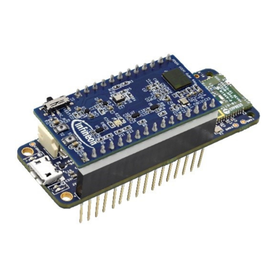
- Page 48 User Guide for XENSIV™ KIT CSK BGT60TR13C Table of contents XENSIV™ BGT60TR13C wing 7.2.1 Wing board components Figure 50, Figure 6 and Table 6 describe the components mounted on the XENSIV™ BGT60TR13C radar wing. Figure 50 Front view of the XENSIV™ BGT60TR13C radar wing Table 6 Onboard HW description Designator...
- Page 49 User Guide for XENSIV™ KIT CSK BGT60TR13C Table of contents Figure 51 Adafruit headers and test points on the back view of the XENSIV™ BGT60TR13C radar wing Table 7 Adafruit feather-compatible pin-out Header Primary PSoC 6 Adafruit Adafruit Details mapping onboard MCU pin feather-...
- Page 50 User Guide for XENSIV™ KIT CSK BGT60TR13C Table of contents J2.1 XRES XRES XRES nRESET Reset button J2.2 3.3 V VDDA, VDDIO VCC Analog voltage for PSOC 6 MCU J2.3 – – Not connected J2.4 – Ground J2.5 Analog P10_0 RGB_RED RGB red color GPIO...
- Page 51 User Guide for XENSIV™ KIT CSK BGT60TR13C Table of contents Appendix A: Hardware design The design of the shield was realized using the Altium PCB design tool. The Altium design files are available on request. Schematics A1.1 Sensors Figure 52 Schematic of XENSIV™...
- Page 52 User Guide for XENSIV™ KIT CSK BGT60TR13C Table of contents Figure 53 Schematic of XENSIV™ DPS368 pressure sensor A1.2 Adafruit feather-compatible headers Figure 4 shows the pin assignment of J1 and J2 on the XENSIV™ BGT60TR13C radar wing. The Adafruit feather- compatible header is used to plug into the CYCBSYSKIT-DEV-01 rapid IoT connect developer kit.
- Page 53 User Guide for XENSIV™ KIT CSK BGT60TR13C Table of contents Figure 55 Schematic of reset (S1) and user button (S2) Figure 56 Schematic of LEDs A1.4 Others Figure 57 shows the board power selection. Figure 57 Board power selection (S3) Figure 58 shows the voltage regulator circuit to provide stable power supply to the radar sensor.
- Page 54 User Guide for XENSIV™ KIT CSK BGT60TR13C Table of contents Figure 59 shows the filter circuit to keep the radar power supply free from spurious emissions. Figure 59 Voltage supply low-pass filters for radar sensor PCB layout The size of the XENSIV™ BGT60TR13C radar wing is 43 mm (L) x 23 mm (W). Figure 60 PCB layout of XENSIV™...
- Page 55 User Guide for XENSIV™ KIT CSK BGT60TR13C Table of contents Ceramic capacitor 0.47 µF 10 0.47 µF V X6S 0201, 0201 LMK063BC6474KPLF Taiyo Yuden LMK063BC6474KPLF Ceramic capacitor 1 µF 6.3 V C11, C14, C15, C16, 1 µF X5R 0201, 0201 GRM033R60J105MEA2D C18, C20, C22, C24, C26 Murata Electronics...
- Page 56 User Guide for XENSIV™ KIT CSK BGT60TR13C XENSIV™ BGT60TR13 Infineon, 60 GHz radar chip Infineon BGT60TR13C original BGT60TR13C C original NCP163AMX180TBG NCP163AMX18 4-XDFN NCP163AMX180TBG 0TBG IC linear regulator 1.8 V ON Semiconductor exposed pad 250 MA 4XDFN NCP163AMX33 NCP163AMX330TBG IC linear...
- Page 57 Yes, the XENSIV™ PAS CO wing and XENSIV™ BGT60TR13C radar wing boards can be stacked together. It is simple to combine the radar code example, i.e. https://github.com/Infineon/mtb-example-sensors-radar- presence-freertos with the XENSIV™ PAS CO code example. Both examples use the FreeRTOS task, which can be easily integrated into a single application.
- Page 58 User Guide for XENSIV™ KIT CSK BGT60TR13C Revision history Revision history Document Date of release Description of changes version V1.0 May 2022 Release version 58 of 59 2022-23-05...
- Page 59 Infineon Technologies hereby disclaims dangerous substances. For information on the types © 2022 Infineon Technologies AG. any and all warranties and liabilities of any kind in question please contact your nearest Infineon All Rights Reserved. (including without limitation warranties of non- Technologies office.
Need help?
Do you have a question about the XENSIV CSK BGT60TR13C and is the answer not in the manual?
Questions and answers