Advertisement
Quick Links
Advertisement

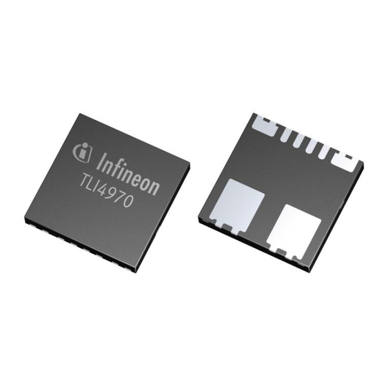
Summary of Contents for Infineon TLI4970-D050T4 CurrentSense Shield2Go
- Page 1 TLI4970-D050T4 CurrentSense Shield2Go Quick Start V1.0.0...
- Page 2 2.5 kV max. rated isolation voltage. The sensor has a 16 bit digital SPI output (13 bit current value). Link to Datasheet Product Page 2018-07-17 Copyright © Infineon Technologies AG 2018. All rights reserved.
- Page 3 Arduino IDE Sales Name S2GO_CUR-SENSE_TLI4970 and OPN • S2GOCURSENSETLI4970TOBO1 Ensure that no voltage applied to any of the pins exceeds the absolute maximum rating of 3.6 V Link to Board Page 2018-07-17 Copyright © Infineon Technologies AG 2018. All rights reserved.
- Page 4 Evaluation Board PCB Details 2018-07-17 Copyright © Infineon Technologies AG 2018. All rights reserved.
-
Page 5: Evaluation Board Schematic
I P - I P _ N G N D T L I 4 9 7 0 - D 0 5 0 T 4 Green area: circuit if head is broken off 2018-07-17 Copyright © Infineon Technologies AG 2018. All rights reserved. - Page 6 Extended information about the Arduino environment. Click here • How to import libraries? Click here • How to install additional boards? Click here • Problems related to Arduino? Click here for troubleshooting • 2018-07-17 Copyright © Infineon Technologies AG 2018. All rights reserved.
- Page 7 (see next slide for further instructions) Additional notes for • installation can be found in the GitHub , e.g. if the library manager is not used https://github.com/Infineon/TLI4970-D050T4-Current-Sensor 2018-07-17 Copyright © Infineon Technologies AG 2018. All rights reserved.
- Page 8 As shown in the picture, please choose the respective library and install it • Regularly check your installed libraries for updates • In case of problems, please visit also our GitHub repository and open an issue • to get further help https://github.com/Infineon/TLI4970-D050T4-Current-Sensor 2018-07-17 Copyright © Infineon Technologies AG 2018. All rights reserved.
- Page 9 Connect the stacked boards to the PC and press the Upload button • Select the related COM port from Tools – Port and open the serial monitor with • the set baud rate (see sketch/code with Serial.begin(<BAUDRATE>);) https://github.com/Infineon/XMC-for-Arduino https://github.com/Infineon/TLI4970-D050T4-Current-Sensor 2018-07-17 Copyright © Infineon Technologies AG 2018. All rights reserved.
-
Page 10: Not Possible
Even if the power is connected to the • 3.3 V pin, the interface lines, e.g. MISO, will still be driven by 5 V Please use appropriate level shifting • for these boards possible 2018-07-17 Copyright © Infineon Technologies AG 2018. All rights reserved.


Need help?
Do you have a question about the TLI4970-D050T4 CurrentSense Shield2Go and is the answer not in the manual?
Questions and answers