Table of Contents
Advertisement
Quick Links
3D Magnetic Sensor 2 Go - TLE493D-A2B6
Low Power 3D Hall Sensor with I²C Interface
TLE493D-A2B6 3D-MS2GO
User Manual
About this document
Scope and purpose
This document provides an introduction to the 3D Magnetic Sensor 2 Go kit and should enable the reader to
efficiently carry out own evaluations with the 3D magnetic sensor TLE493D-A2B6.
Intended audience
This document is aimed at everyone who wants to work with the 3D Magnetic Sensor 2 Go evaluation kit.
User Manual
Please read the Important Notice and Warnings at the end of this document
1.0
www.infineon.com
2018-05-16
Arrow.com.
Downloaded from
Advertisement
Table of Contents

Related Manuals for Infineon TLE493D-A2B6


Summary of Contents for Infineon TLE493D-A2B6
-
Page 1: User Manual
Scope and purpose This document provides an introduction to the 3D Magnetic Sensor 2 Go kit and should enable the reader to efficiently carry out own evaluations with the 3D magnetic sensor TLE493D-A2B6. Intended audience This document is aimed at everyone who wants to work with the 3D Magnetic Sensor 2 Go evaluation kit. -
Page 2: Table Of Contents
3D Magnetic Sensor 2 Go - TLE493D-A2B6 Low Power 3D Hall Sensor with I²C Interface Table of contents Table of contents User Manual ................1 About this document . -
Page 3: Introduction
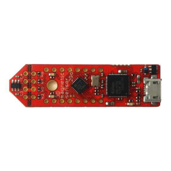
14mm 50mm Figure 1 3D Magnetic Sensor 2 Go EvalBoard Software The required software to run the kit can be found at the Infineon web site. For further information refer to the chapter Software installation. The software package contains: •... - Page 4 3D Magnetic Sensor 2 Go - TLE493D-A2B6 Low Power 3D Hall Sensor with I²C Interface Introduction In addition, Infineon offers magnet heads which can be mounted on the EvalBoard. Currently two magnetic heads are available, a joystick and a rotation knob. Table 1...
- Page 5 3D Magnetic Sensor 2 Go - TLE493D-A2B6 Low Power 3D Hall Sensor with I²C Interface Introduction 10mm Figure 4 Magnet used in the rotation knob magnet head User Manual 2018-05-16 Arrow.com. Arrow.com. Arrow.com. Arrow.com. Arrow.com. Downloaded from Downloaded from Downloaded from...
-
Page 6: Evalboard Description
EvalBoard description The evaluation board (EvalBoard) is a ready-to-use printed circuit board (PCB) which contains: • The 3D magnetic sensor TLE493D-A2B6. For the availability of 3D Magnetic Sensor 2 Go kits with different sensor variants check the Infineon web page: https://www.infineon.com/cms/en/product/sensor/ magnetic-position-sensor/3d-magnetic-sensor/ •... -
Page 7: Pin Header Connector
3D Magnetic Sensor 2 Go - TLE493D-A2B6 Low Power 3D Hall Sensor with I²C Interface EvalBoard description It is not recommended to apply an additional power supply to the V pin of X1 (3.3 V) when the board is powered via USB, because the 3.3 V supply could drive against the on-board power supply. The V pin can be used to power an external circuit. -
Page 8: Evalboard Schematics
3D Magnetic Sensor 2 Go - TLE493D-A2B6 Low Power 3D Hall Sensor with I²C Interface EvalBoard description EvalBoard schematics The schematics of the different blocks from the EvalBoard of the3D Magnetic Sensor 2 Go kit are provided in this chapter. They can be used to design customized PCBs. The user (integrator) is responsible for the correct functioning on system level as well as for the validation and testing. - Page 9 3D Magnetic Sensor 2 Go - TLE493D-A2B6 Low Power 3D Hall Sensor with I²C Interface EvalBoard description Figure 9 EvalBoard schematic: the LEDs for user configuration (connected to XMC1100 pins) Figure 10 EvalBoard schematic: the XMC1100 microcontroller and pin headers...
- Page 10 3D Magnetic Sensor 2 Go - TLE493D-A2B6 Low Power 3D Hall Sensor with I²C Interface EvalBoard description Figure 11 EvalBoard schematic: the Debug connection User Manual 2018-05-16 Arrow.com. Arrow.com. Arrow.com. Arrow.com. Arrow.com. Arrow.com. Arrow.com. Arrow.com. Arrow.com. Arrow.com. Downloaded from Downloaded from...
- Page 11 3D Magnetic Sensor 2 Go - TLE493D-A2B6 Low Power 3D Hall Sensor with I²C Interface EvalBoard description Figure 12 EvalBoard schematic: the XMC4200 microcontroller and micro USB connector User Manual 2018-05-16 Arrow.com. Arrow.com. Arrow.com. Arrow.com. Arrow.com. Arrow.com. Arrow.com. Arrow.com. Arrow.com.
-
Page 12: Software Installation
Steps Download the software. Follow the link below to reach the Sensor 2 Go information page on the Infineon website. As shown in Figure 13, you can find the download link for the latest version of the 3D Magnetic Sensor 2 Go GUI on the right hand side. - Page 13 3D Magnetic Sensor 2 Go - TLE493D-A2B6 Low Power 3D Hall Sensor with I²C Interface Software installation Figure 14 Start the software installation Read the license agreement carefully and tick the box to accept the terms. Click Next. Figure 15 Accept the license agreement Choose your installation path and check that the SEGGER J-Link driver will be installed.
- Page 14 3D Magnetic Sensor 2 Go - TLE493D-A2B6 Low Power 3D Hall Sensor with I²C Interface Software installation Figure 16 Select you installation folder Confirm the installation settings by clicking on Install. Figure 17 Confirm the installation Once the installation is complete, click on Finish to close the installer.
-
Page 15: Driver Installation
Software installation Figure 18 Installation finished You can now start the evaluation software. Open the start menu, browse to Infineon Technologies > 3D Sensor 2go Kit and open the application by clicking on 3D 2Go. Figure 19 Shortcut to the 3D Magnetic 2Go evaluation software (GUI) - Page 16 3D Magnetic Sensor 2 Go - TLE493D-A2B6 Low Power 3D Hall Sensor with I²C Interface Software installation Figure 20 J-Link driver setup Read and accept the license agreement. Click on I Agree. Figure 21 J-Link license agreement Check that the "Install USB Driver for J-Link" option is active. Click on Next.
- Page 17 3D Magnetic Sensor 2 Go - TLE493D-A2B6 Low Power 3D Hall Sensor with I²C Interface Software installation Figure 22 J-Link installation options Choose the installation folder. It is recommend to keep the default settings. Click on Install. Now the installation should be executed.
- Page 18 3D Magnetic Sensor 2 Go - TLE493D-A2B6 Low Power 3D Hall Sensor with I²C Interface Software installation Figure 24 J-Link installation complete User Manual 2018-05-16 Arrow.com. Arrow.com. Arrow.com. Arrow.com. Arrow.com. Arrow.com. Arrow.com. Arrow.com. Arrow.com. Arrow.com. Arrow.com. Arrow.com. Arrow.com. Arrow.com. Arrow.com.
-
Page 19: 3D Magnetic Sensor Evaluation
3D magnetic sensor evaluation 3D magnetic sensor evaluation This chapter describes how the GUI can be used to make first evaluations with Infineon's 3D magnetic sensor. Getting started Once the software is installed, the following steps are necessary to do the first magnetic measurements. -
Page 20: Graph View
3D Magnetic Sensor 2 Go - TLE493D-A2B6 Low Power 3D Hall Sensor with I²C Interface 3D magnetic sensor evaluation Table 4 Sensor modes (continued) Sensor mode Description Master controlled Sensor measurements are triggered by the microcontroller, which mode enables high flexibility. -
Page 21: Joystick View
The software measures the magnetic field in all three dimensions and calculates the angles necessary to determine the joystick position. Further information is given in the application note "Infineon 3D Magnetic Sensor - How to Make a Magnetic Design for Joystick" which can be found on the Infineon home page. Figure 27... -
Page 22: Revision History
3D Magnetic Sensor 2 Go - TLE493D-A2B6 Low Power 3D Hall Sensor with I²C Interface Revision history Figure 28 Polar coordinates Revision history Document Date of Description of changes version release 2018-05-16 Initial version. 2018-10-12 Title page updated. User Manual 2018-05-16 Arrow.com. -
Page 23: Disclaimer
Infineon Technologies, All Rights Reserved. any kind, including without limitation warranties of Infineon Technologies’ products may not be used in non-infringement of intellectual property rights of any any applications where a failure of the product or third party.
Need help?
Do you have a question about the TLE493D-A2B6 and is the answer not in the manual?
Questions and answers