Table of Contents
Advertisement
Quick Links
To our customers,
st
On April 1
, 2010, NEC Electronics Corporation merged with Renesas Technology
Corporation, and Renesas Electronics Corporation took over all the business of both
companies. Therefore, although the old company name remains in this document, it is a valid
Renesas Electronics document. We appreciate your understanding.
Issued by: Renesas Electronics Corporation (http://www.renesas.com)
Send any inquiries to http://www.renesas.com/inquiry.
Old Company Name in Catalogs and Other Documents
Renesas Electronics website:
http://www.renesas.com
st
April 1
, 2010
Renesas Electronics Corporation
Advertisement
Table of Contents

Related Manuals for Renesas SDI Emulator System M32100T-EZ-E


Summary of Contents for Renesas SDI Emulator System M32100T-EZ-E
- Page 1 On April 1 , 2010, NEC Electronics Corporation merged with Renesas Technology Corporation, and Renesas Electronics Corporation took over all the business of both companies. Therefore, although the old company name remains in this document, it is a valid Renesas Electronics document. We appreciate your understanding.
- Page 2 Renesas Electronics. Renesas Electronics shall not be in any way liable for any damages or losses incurred by you or third parties arising from the use of any Renesas Electronics product for an application categorized as “Specific”...
- Page 3 M32100T-EZ-E User’s Manual SDI Emulator System for M32R Family Rev.2.00 2003.09...
- Page 4 • These materials are intended as a reference to assist our customers in the selection of the Renesas Technology product best suited to the customer's application; they do not convey any license under any intellectual property rights, or any other rights, belonging to Renesas Technology Corporation, Renesas Solutions Corporation or a third party.
-
Page 5: Precautions For Safety
Preface The M32100T-EZ-E is an emulator system using the internal debug interface SDI (Scalable Debug Interface) of the M32R Family MCUs. Using with the emulator debugger PD32RM included in this product package, it is possible to develop programs for MCUs on which the SDI is mounted. This user's manual mainly describes specifications of the M32100T-EZ-E emulator system and how to setup it. -
Page 6: Table Of Contents
Contents Chapter 1. Precautions for Safety ... 5 1.1 Safety Symbols and Meanings ... 6 Chapter 2. Preparation ... 13 2.1 Terminology ... 14 2.2 Package Components ... 15 2.3 System Configuration of the M32100T-EZ-E ... 16 2.4 Name of Each Part ... 17 Chapter 3. -
Page 7: Chapter 1. Precautions For Safety
Chapter 1. Precautions for Safety This chapter describes precautions for using this product safely and properly. For precautions of the emulator and emulator debugger, refer to each user's manual. 1.1 Safety Symbols and Meanings ... 6 Warnings for AC Power Supply ... 7 WARNING Warnings to Be Taken for This Product ... -
Page 8: Safety Symbols And Meanings
Chapter 1. Precautions for Safety In both the user's manual and on the product itself, several icons are used to insure proper handling of this product and also to prevent injuries to you or other persons, or damage to your properties. This chapter describes the precautions which should be taken in order to use this product safely and properly. -
Page 9: Warnings For Ac Power Supply
Warnings for AC Power Supply: • Power is supplied via the USB interface cable. Therefore, do not try to modify or forcibly insert it. It may cause electric shock and/or fire. • Do not supply power from the host machine to which this product is connected to other device(s). •... -
Page 10: Caution
Cautions for Power Supply: • Power is supplied from the host machine to this product via the USB interface cable. • Switch on and off this product by the USB interface cable. Cautions for Powering Up Sequence: • When turning on power, activate the emulator first and then the target system. •... -
Page 11: Important
(3) Debug specifications dependent on MCU model (Section 5.1) (4) Other cautions and restrictions dependent on MCU model • Download the latest release notes and MCU file from the Renesas Tool Homepage. http://www.renesas.com/eng/products/mpumcu/toolhp/mcu/m32r_e.htm Note on Stack Capacity and Stack Pointer: •... -
Page 12: Notes On Target Program Execution In Real-Time
Note on Target Program Execution in Real-time: • The DMA controller for the emulator incorporated in the MCU is used for the memory references/ settings during target program execution. Therefore, for the memory references/settings during target program execution, the bus-cycle by the DMA controller occurs. Note on Specifying Breakpoints: •... -
Page 13: Notes On Target System
Notes on Target System: • The power to the MCU can be turned off and back on again during target program execution. However, because the emulator makes various settings on the MCU after it is powered back on again, it takes a little longer time than when not using the emulator before the MCU can start running the program after being powered up again. - Page 14 MEMO ( 12 / 42 )
-
Page 15: Chapter 2. Preparation
This chapter describes the package components, the system configuration and the preparation for using this product for the first time. 2.1 Terminology ... 14 2.2 Package Components ... 15 2.3 System Configuration of the M32100T-EZ-E ... 16 (1) JTAG Connection ... 16 2.4 Name of Each Part ... -
Page 16: Terminology
Chapter 2. Preparation 2.1 Terminology Some specific words used in this user's manual are defined as follows: Emulator system This means an emulator system built around the M32100T-EZ-E emulator. The M32100T-EZ-E emulator system is configured with an emulator, host machine, emulator debugger and target board. Emulator (M32100T-EZ-E) This means an emulator for the M32R Family MCUs on which the debug interface SDI (Scalable Debug Interface) is mounted. -
Page 17: Package Components
Release notes (Japanese) Hardware tool user registration FAX sheet * The latest version of the emulator debugger PD32RM is downloadable from the Renesas Tool Homepage (http://www.renesas.com/eng/products/mpumcu/toolhp/mcu/m32r_e.htm). * Please keep the M32100T-EZ-E's packing box and cushion material in your place for reuse at a later time when sending your product for repair or other purposes. -
Page 18: System Configuration Of The M32100T-Ez-E
2.3 System Configuration of the M32100T-EZ-E Because the M32100T-EZ-E uses a debug interface SDI (Scale Debug Interface) built in the MCU, JTAG connection is available, which can directly control the MCU installed in the target board. (1) JTAG Connection The system configuration when using the M32100T-EZ-E by JTAG connection is shown below. (1) Host machine (Personal computer) (2) Emulator (M32100T-EZ-E) (3) Emulator debugger (PD32RM) -
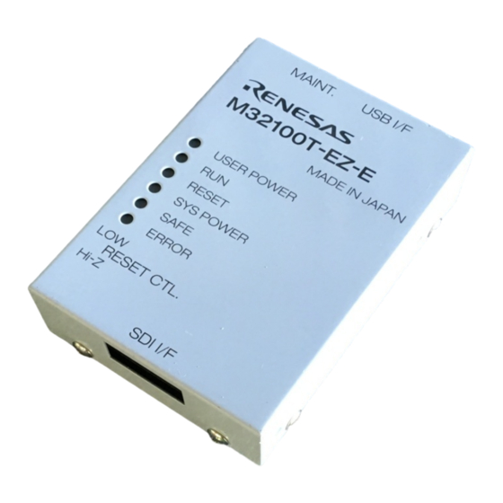
Page 19: Name Of Each Part
2.4 Name of Each Part Here explains the name and function of each part. (1) Names and Functions of Parts on the Upper Panel Emulator M32100T-EZ-E Figure 2.2 Name of each part on the upper panel 1. System status LEDs The system status LEDs indicate the M32100T-EZ-E emulator's power supply, firmware operating status, etc. - Page 20 2. Target status LEDs The target status LEDs indicate the status of the target MCU's operation and the target board's power supply, etc. Table 2.2 lists the definitions of the target status LEDs. Take note of the fact that the target status LEDs cannot show the MCU status properly after the emulator is powered on until the emulator debugger gets started.
-
Page 21: Names And Functions Of Parts On The Side Panel
(2) Names and Functions of Parts on the Side Panel Figure 2.3 Name of each part on the side panel 1. Reset control switch The reset control switch selects the status of the /RESET signal to the target MCU after the emulator power is turned on until the emulator debugger gets started. -
Page 22: Names And Functions Of Parts On The Rear Panel
(4) Names and Functions of Parts on the Rear Panel USB interface connector Figure 2.5 Name of each part on the rear panel 1. Maintenance switch If this switch is pressed within 2 seconds after turning on the power, the emulator switches to maintenance mode for downloading firmware. -
Page 23: Chapter 3. Setup
This chapter describes switch settings required for using this product and how to connect this product to the host machine and the target system. 3.1 Connecting the Host Machine ... 22 3.2 Connecting the Target System ... 23 (1) Connecting the SDI Interface Connector ... 23 (2) SDI MCU Control Interface Connector ... -
Page 24: Connecting The Host Machine
Chapter 3. Setup Figure 3.1 shows how to setup the M32100T-EZ-E. Install the emulator debugger before setting up the M32100T-EZ-E. For installing the emulator debugger, refer to the PD32RM release notes. * By connecting the USB interface cable, power is supplied to the M32100T-EZ-E. Figure 3.1 Setup procedure 3.1 Connecting the Host Machine The emulator is connected to the host machine via the USB interface. -
Page 25: Connecting The Target System
3.2 Connecting the Target System The M32100T-EZ-E supports JTAG connection to connect to the target board. To connect the emulator to the target board using the JTAG connection method, you should have the SDI MCU control interface connector on the target board. Connect the M32100T-EZ-E connector to the SDI interface connector on the target board using the provided cable. - Page 26 J1: Open when connecting the emulator, in other cases, 1-2 short J2: 1-2 short when connecting the emulator, in other cases, 2-3 short Figure 3.4 Sample circuit of the SDI MCU control interface The following must be observed in designing a target system when you connect the SDI MCU control interface connector to the target system.
-
Page 27: Emulator Side Circuit Diagram
(3) Emulator Side Circuit Diagram Figure 3.5 shows the circuit diagram in the emulator of the SDI trace interface part, and Table 3.3 lists the explanation of the circuit diagram. Figure 3.5 Circuit diagram of the emulator side of the SDI interface Table 3.3 Parts in the emulator Part No. - Page 28 MEMO ( 26 / 42 )
-
Page 29: Chapter 4. Usage
This chapter describes from turning on the power of this product to starting up the emulator debugger. 4.1 Turning on the Power Supply ... 28 (1) Checking the Connections of the System ... 28 (2) Turning On/Off the Power Supply... 28 4.2 Downloading Firmware ... -
Page 30: Turning On The Power Supply
Chapter 4. Usage 4.1 Turning on the Power Supply (1) Checking the Connections of the System Before turning on the power, check the connections of the host machine, communications interface cable, emulator and target system. (2) Turning On/Off the Power Supply •... -
Page 31: Downloading Firmware
4.2 Downloading Firmware (1) When It is Necessary to Download Firmware It is necessary to download the firmware in the occasions listed below. Generally, these are detected when the emulator debugger starts up, then downloading the firmware is started. (1) When you use this product for the first time (2) When the firmware has been upgraded (3) When the emulator debugger has been upgraded Redownload the firmware when the power supply is shut off or when the communication interface... - Page 32 MEMO ( 30 / 42 )
-
Page 33: Chapter 5. Specifications
Chapter 5. Specifications This chapter describes specifications of this product. 5.1 Specifications ... 32 ( 31 / 42 ) -
Page 34: Specifications
Use environment Storage environment Overseas standards *1 The latest list of the applicable MCUs is available on the Renesas Tool Homepage. http://www.renesas.com/eng/products/mpumcu/toolhp/mcu/m32r_e.htm *2 Depends on the MCU specifications. For details, see the release notes. M32R MCUs integrating SDI whose operation verification has... -
Page 35: Chapter 6. Troubleshooting
Chapter 6. Troubleshooting This chapter describes how to troubleshoot when this product does not work properly. 6.1 Flowchart to Remedy Troubles ... 34 6.2 When the Emulator Debugger Does Not Start up Properly... 35 (1) When the LED Display of the M32100T-EZ-E is Abnormal ... 35 (2) Errors Occur When the Emulator Debugger Starts Up... -
Page 36: Flowchart To Remedy Troubles
Chapter 6. Troubleshooting 6.1 Flowchart to Remedy Troubles Figure 6.1 shows the flowchart to remedy troubles from when the emulator is activated until the emulator debugger gets started. Check this while the target system is disconnected. Turning on the emulator system Init dialog box of the emulator Program window of the emulator debugger displayed Figure 6.1 Flowchart to remedy troubles... -
Page 37: When The Emulator Debugger Does Not Start Up Properly
6.2 When the Emulator Debugger Does Not Start Up Properly (1) When the LED Display of the M32100T-EZ-E is Abnormal Table 6.1 LED's abnormal display and its checkpoints Error LEDs do not light up. The SAFE or ERROR LED of "STATUS OF SYSTEM"... -
Page 38: Errors Occur When The Emulator Debugger Starts Up
(2) Errors Occur When the Emulator Debugger Starts Up Table 6.2 Checkpoints of errors when starting up the emulator debugger Error • Communication ERROR. Can't send data. • The version of PD32RM and the firmware on the target are not same. •... -
Page 39: Chapter 7. Maintenance And Guarantee
Chapter 7. Maintenance and Guarantee This chapter describes how to maintenance, repair provisions and how to request for repair. 7.1 Maintenance... 38 7.2 Guarantee ... 38 7.3 Repair Provisions ... 38 7.4 How to Request for Repair ... 39 ( 37 / 42 ) -
Page 40: Maintenance
12 months after purchase while being used under good conditions by observing the Precautions for Safety described in "Chapter 1. Precautions for Safety", Renesas will repair the fault free-of-charge. (This provision does not apply to emulation pods leased to you.) When repair is required, contact your local distributor. -
Page 41: How To Request For Repair
Distributors After checking the contents of fault, the distributor should please send the faulty M32100T-EZ-E along with the Repair Request Sheet to Renesas Solutions. Renesas Solutions Corp. When the faulty M32100T-EZ-E is repaired, it will be returned to the customer at the earliest convenience. - Page 42 MEMO ( 40 / 42 )
- Page 43 M32100T-EZ-E User's Manual Rev.2.00 September 1, 2003 REJ10J0002-0200Z COPYRIGHT ©2003 RENESAS TECHNOLOGY CORPORATION AND RENESAS SOLUTIONS CORPORATION ALL RIGHTS RESERVED...
- Page 44 M32100T-EZ-E User’s Manual 1753, Shimonumabe, Nakahara-ku, Kawasaki-shi, Kanagawa 211-8668 Japan REJ10J0002-0200Z...
Need help?
Do you have a question about the SDI Emulator System M32100T-EZ-E and is the answer not in the manual?
Questions and answers