
Related Manuals for Dalsa Shad-o-Scan 3001


Summary of Contents for Dalsa Shad-o-Scan 3001
- Page 1 Teledyne DALSA Shad-o-Scan 3001/4501 Detector User Manual GigE model Rev04, January 2022 DNR-310-15-21005 http://www.teledynedalsa.com/ndt...
- Page 2 Shad-o-Scan User Manual, Rev04 © 2022 Teledyne DALSA. All information provided in this manual is believed to be accurate and reliable. No responsibility is assumed by Teledyne DALSA for its use. Teledyne DALSA reserves the right to make changes to this information without notice. Reproduction of this manual in whole or in part, by any means, is prohibited without prior permission having been obtained from Teledyne DALSA.
-
Page 3: Table Of Contents
Read-Out Modes ....................36 Binning Modes, D-TDI lines and Scanning Speed ..........38 Frame Concatenation ..................38 Image Format Control ....................39 Image Processing Control ..................39 Defect Pixel Correction ..................42 Flat Field Correction ..................42 Shad-o-Scan 3001/4501 X-Ray Detector Teledyne DALSA... - Page 4 FFC Calculation ....................43 Defect Maps ...................... 44 Dark/Gain Maps ....................48 File Format ......................48 Firmware Update...................... 51 Mechanical Interface ____________________________________________ 54 Mechanical Dimensions ................... 54 Appendix A ____________________________________________________ 56 Revision History ________________________________________________ 56 Shad-o-Scan 3001/4501 X-Ray Detector Teledyne DALSA...
-
Page 5: System Precautions And Safety
Teledyne DALSA assumes no responsibility for the user’s failure to comply with these requirements. Warning: The product, when installed, is subject to exposure from X-rays during operation. -
Page 6: Labels
Stacking Teledyne DALSA does not recommend that the user stack the product or use it adjacent to other equipment. If this arrangement is unavoidable, then the (End-)user must ensure that there is adequate airflow around the detector and that normal operation conditions are maintained. -
Page 7: Symbols
Electrical and Electronic Equipment (Do not dispose in household bin) Refer to instruction manual CE-marking On-product connector symbols: Functional earth GigE interface connector DC supply connector Trigger connector As used in this manual: Caution General warning sign Shad-o-Scan 3001/4501 X-Ray Detector Teledyne DALSA... -
Page 8: General Safety Instructions
Warning: The use of accessories, power supplies and cables other than those specified, with the exception of cables sold by Teledyne DALSA as replacement parts, may result in increased emission or decreased immunity of the Shad-o-Scan 3001/4501 Detector. Static precautions Observe proper ESD/static control procedures when handling system components. -
Page 9: Regulatory Compliance
Protecting the Detector Front Cover Carbon strip The carbon strip in the front cover of the detector should be treated with care, as scratches or debris in this area may produce artifacts in the X-ray image. Shad-o-Scan 3001/4501 X-Ray Detector Teledyne DALSA... -
Page 10: Open Source Software Licenses
The WEEE symbol on the product indicates that the product cannot be disposed of with other household or municipal waste. Teledyne DALSA has labeled its products with the WEEE symbol to alert the customers that products bearing this label should not be disposed of in the landfill. - Page 11 The correct disposal of your equipment will help conserve the natural resources and ensure that the equipment is recycled in a manner that protects the environment and human health. Shad-o-Scan 3001/4501 X-Ray Detector Teledyne DALSA...
-
Page 12: The Shad-O-Scan Detector
Shad-o-Scan User Manual, Rev04 The Shad-o-Scan Detector A description of a limited functional specification of the Shad-o-Scan 3001 /4501 detector can be found in the latest product specification or datasheet. Please contact sales.rad-icon@TeledyneDALSA.com or visit www.TeledyneDALSA.com/ndt/ for information on how to obtain the latest datasheet or other product documentation. -
Page 13: Setting Up The Detector
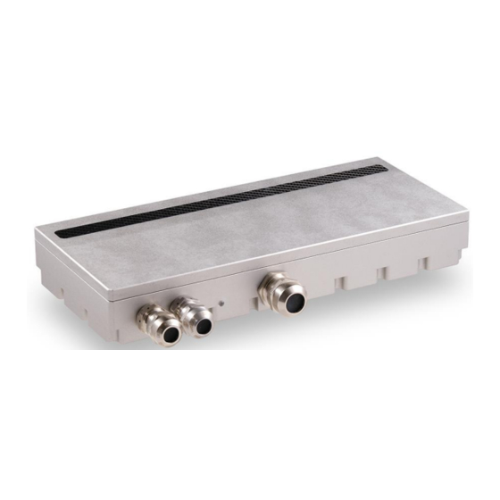
One 2-pin Lemo connector for power Lemo EXG.0B.302.HLN Mating connector: straight type: FGG.0B.302.CLAD52 • One 4-pin Lemo connector for triggering Lemo EXG.0B.304.HLN Mating connectors: straight type: FGG.0B.304.CLAD52 5GigE Trigger Power Status connector connector connector Shad-o-Scan 3001/4501 X-Ray Detector Teledyne DALSA... - Page 14 The detector is equipped with an orange/red LED used to display the status of the detector’s operation. The table below summarizes the operating states of the detector and the corresponding LED states. Color Of Status LED Meaning Detector starting up, Programming Detector is off or in normal operation Shad-o-Scan 3001/4501 X-Ray Detector Teledyne DALSA...
- Page 15 Use high-quality linear supplies of SELV type and/or EN 60601-1 compliant. Note: If your power supply does not meet these requirements, the detector performance specifications cannot be guaranteed. Trigger Connector The trigger circuitry inside the detector is shown in the figure below. Shad-o-Scan 3001/4501 X-Ray Detector Teledyne DALSA...
- Page 16 6V. Note 2: maximum reverse voltage across cathode and anode is 6V. Description Input circuitry Trigger In Inside the detector the connection for the input is as in below drawing: Shad-o-Scan 3001/4501 X-Ray Detector Teledyne DALSA...
- Page 17 4pin LEMO Inside Detector Connector Trigger Output Collector + SMA58J I_lim Trigger Output Emitter - TCMT1600 FPGA Trigger Input Anode + Trigger Input Cathode - Shield connector to mechanical ground Voltage range of Trigger output: Shad-o-Scan 3001/4501 X-Ray Detector Teledyne DALSA...
- Page 18 Trigger Output Emitter” is pulled down with a resistor (range 100 Ohm to 1k Ohm) to ground. Then “Trigger-Out” is active high (= integration state of detector). In this document the state of “Trigger-Out” is “active” (integrating) or “not-active” (reading/reset of pixels). Shad-o-Scan 3001/4501 X-Ray Detector Teledyne DALSA...
-
Page 19: Setting Up The Detector
A NIC with Jumbo packet support up to 9014 bytes is required to receive streaming video, preferably with a PCI Express slot. Teledyne DALSA advises to use the 5G adapter Network Interface Card (NIC) which is a low cost but high performance and reliable adapter with a PCI Express slot. -
Page 20: Software Installation
Obtain software Website Visit the Teledyne DALSA website to download the latest free version of the Sapera LT SDK, including the CamExpert image viewer: http://www.teledynedalsa.com/imaging/products/software/sapera/lt/download/ The download is free after filling out the on-line registration form. Make sure to select “Full SDK”... -
Page 21: Gige Vision Framework For Sapera Lt Installation
Some system and network card configurations may have difficulty streaming and handling jumbo packet data. If the system is having issues than it is advisable to disable the Jumbo Packet setting and use standard size packets of 1500 bytes for your application. Shad-o-Scan 3001/4501 X-Ray Detector Teledyne DALSA... - Page 22 We recommend increasing the receive buffer size to the maximum permitted by the network card, in order to provide more buffering capacity when needed. Shad-o-Scan 3001/4501 X-Ray Detector Teledyne DALSA...
- Page 23 Again, by combining network equipment that can operate at wire-speed and allocating a different network interface port for each detector in the system, we can ensure these pause requests will not be used. Shad-o-Scan 3001/4501 X-Ray Detector Teledyne DALSA...
-
Page 24: Connecting
Detector Network Interface Card on host system to which the detector is connected The default assigned detector IP address can be modified using the Teledyne DALSA Network Configuration Tool, which is part of the installation package. Shad-o-Scan 3001/4501 X-Ray Detector... -
Page 25: Quick Test With Camexpert
A digital test pattern can be selected for testing network/computer bandwidth issues. ▪ Refer to the Teledyne DALSA Network Imaging package manual if error messages are shown in the Output Messages pane. But first, increase the value of the Interpacket Delay feature available from the GigE Vision TransportLayer Category group in CamExpert. -
Page 26: Acquiring Images
After the Freeze button is pressed the detector ignores any additional triggers and no additional images are acquired User Controlled: Send Arm, Start, Stop, Abort commands to the detector to manually control the image acquisition. Shad-o-Scan 3001/4501 X-Ray Detector Teledyne DALSA... -
Page 27: Operational Reference
▪ Display pane: Provides a live or single frame acquisition display. Frame buffer parameters are shown in an information bar above the image window. Shad-o-Scan 3001/4501 X-Ray Detector Teledyne DALSA... - Page 28 CamExpert presents detector features based on their visibility attribute. CamExpert provides quick Visibility level selection (Beginner/Expert/Guru) via controls below each Category Parameter list [ << Less More>>]. The user can also choose the Visibility level (Beginner/Expert/Guru) from the View – Parameters Options menu. Shad-o-Scan 3001/4501 X-Ray Detector Teledyne DALSA...
-
Page 29: Camera Information
Load factory default feature Factory Setting FactorySetting settings. Select the user defined UserSet1 UserSet1 configuration UserSet 1 as the Power-up Configuration. Select the user defined UserSet2 UserSet2 configuration UserSet 2 as the Power-up Configuration. Shad-o-Scan 3001/4501 X-Ray Detector Teledyne DALSA... - Page 30 User Set Selector Save Configuration UserSetSave feature. The user sets are located on the camera in non-volatile memory The temperature on the Temperature DeviceTemperature processing board in degrees Celcius Shad-o-Scan 3001/4501 X-Ray Detector Teledyne DALSA...
-
Page 31: Camera Configuration Selection Dialog
User Set 1 or 2 and click Save. Select a saved user set and click Load to restore a saved configuration. Note: A firmware reboot (power cycling) may be required after resetting the user set configuration to the Factory Setting. Shad-o-Scan 3001/4501 X-Ray Detector Teledyne DALSA... -
Page 32: Sensor Control
0, max 3072 (for the 3001), max Horizontal Offset Horizontal Offset 4608 (for the 4501) Multiple of 4 Vertical start position for ROI mode; Vertical Offset Vertical Offset min 0, max 64 Multiple of 4 Shad-o-Scan 3001/4501 X-Ray Detector Teledyne DALSA... -
Page 33: Read-Out Mode
OffsetX, OffsetY, Width, and Height. The resulting image generated by the device has Width time Height pixels. OffsetX and OffsetY are given with respect to the upper left corner of the image which has the coordinate (0, 0) (see Figure). Shad-o-Scan 3001/4501 X-Ray Detector Teledyne DALSA... -
Page 34: Digital Time Delay Integration (Dtdi)
In order to achieve a correct Digital TDI integrated images, the sensor ReadOut Direction must be set to correspond with the detector scan direction. The sensor ReadOut Direction shall be set as shown in the figure below. Shad-o-Scan 3001/4501 X-Ray Detector Teledyne DALSA... - Page 35 Due to the inherent signal accumulation nature of the Time Delay Integration (DTDI) operation, the output signal shows a “run-in” behavior during the first line outputs, for a period equal to the total number of rows that are summed. Shad-o-Scan 3001/4501 X-Ray Detector Teledyne DALSA...
-
Page 36: Read-Out Modes
C: frame blanking 1 us – 60s 1 us – 60s 1 us – 60s 1 us – 60s 1 us – 60s 1 us – 60s interval (Exposure Time) (A-B) Figure timing diagram 'free running' Shad-o-Scan 3001/4501 X-Ray Detector Teledyne DALSA... - Page 37 0.369 ms 0.513 ms 0.369 ms 0.513 ms time B: readout time 0.712 ms 1.014 ms 0.369 ms 0.513 ms 0.369 ms 0.513 ms C: frame blanking interval (A-B) Figure timing diagram 'Trigger Mode' Shad-o-Scan 3001/4501 X-Ray Detector Teledyne DALSA...
-
Page 38: Binning Modes, D-Tdi Lines And Scanning Speed
The tables below shows the predicted maximum scanning speeds for both Shad-o- Scan 3001 and 4501 detectors vs. binning modes and number of Digital TDI lines at maximum framerate. Shad-o-Scan 3001: Binning Mode, Digital TDI lines and Scanning Speed Number of Binning mode 1x1... -
Page 39: Image Format Control
Flat Field Correction (FFC), a combination of black (offset) and gain correction, in which spatial non-uniformities in the images due to detector or system (X-ray source, collimation) characteristics are corrected to reduce fixed pattern noise and optimize dynamic range. Shad-o-Scan 3001/4501 X-Ray Detector Teledyne DALSA... - Page 40 Select automatic or manual FFC map Auto selection Auto Auto Automatic set FFC maps Manual Manual Manual set FFC maps Factory/Customer FFCFileSetSelect Indicates the mode of Customer or Auto Map Select CustomerMode Factory map Shad-o-Scan 3001/4501 X-Ray Detector Teledyne DALSA...
- Page 41 Invalid Dark Map InvalidDarkMap Invalid Dark Map Invalid Gain Map InvalidGainMap Invalid Gain Map Undefined Error UndefinedError Undefined Error Not Initialised NotInitialised Not Initialised DPC Enable DPCEnable Turns On/Off Defect Pixel Correction On: Enabled Off: Disabled Shad-o-Scan 3001/4501 X-Ray Detector Teledyne DALSA...
-
Page 42: Defect Pixel Correction
In detector volatile memory, the captured image will be added to the current dark reference map using the FFC New Dark Weight value. The dark reference map stored in the detector’s non-volatile memory, which is loaded on power-up, is not automatically updated. Shad-o-Scan 3001/4501 X-Ray Detector Teledyne DALSA... -
Page 43: Ffc Calculation
Fixed value added to prevent noise clipping File Format The file format of a dark and gain maps are as follows: A header indicates the specification of the dark or gain map. The 32 bytes header format is described below: Shad-o-Scan 3001/4501 X-Ray Detector Teledyne DALSA... -
Page 44: Defect Maps
Defect pixel reference maps are stored in detector non-volatile memory. These maps contain information on the position of defective (or deviating) pixels, required for Defect Pixel Correction (DPC). These maps are detector-specific and are generated during Teledyne DALSA factory calibration. Shad-o-Scan 3001/4501 X-Ray Detector Teledyne DALSA... - Page 45 Only one bit per pixel is used to indicate the defect status (0 = no defect, 1 = defect). The defect status data per pixel is ordered row-by-row, left-to-right and top- to-bottom in an image displayed on a computer screen). The 32 bytes header format is described below: Shad-o-Scan 3001/4501 X-Ray Detector Teledyne DALSA...
- Page 46 Binning: Horizontal 2, vertical 2 (offset 24, 22) • FullWell: HFW And LFW (offset 25, 0x05, 0b00000101 ) • Readout direction: Top to Bottom, Right to Left (offset 26, 01) Defect pixels; Pixels Value 0..728 731..826 828..836 837..839 Shad-o-Scan 3001/4501 X-Ray Detector Teledyne DALSA...
- Page 47 When attempting to upload a new defect pixel map, the detector will check the file header. In case the header is incorrect, uploading the file will be blocked with error message: The selected file write access to the device failed! Shad-o-Scan 3001/4501 X-Ray Detector Teledyne DALSA...
-
Page 48: Dark/Gain Maps
The file format of the dark (or gain) maps is as follows: a header indicates the specification of the map and will be followed by a data block with the dark (or gain) information per pixel. The 32 bytes header format is described below: Shad-o-Scan 3001/4501 X-Ray Detector Teledyne DALSA... - Page 49 For optimal gain correction, the Gain reference map should be created at an exposure of approximately 25% of the full scale output signal. To create a new Gain map: • Average at least 16 images captured by the detector, without any object placed in the X-ray beam. Shad-o-Scan 3001/4501 X-Ray Detector Teledyne DALSA...
- Page 50 FFC_map0 till FFC_Map11 are the storage locations for Dark- and Gain Maps. The Factory maps are stored in a fixed order. The file type per map is mentioned in the Description. The Customer dark- and gain maps however can be stored in a random order. Shad-o-Scan 3001/4501 X-Ray Detector Teledyne DALSA...
-
Page 51: Firmware Update
Through the CamExpert file access control, a firmware update can be performed. Use the browse button to select a firmware file which has the extension CBF. The filename has the following format: MODELNAMEFWVER.cbf The modelname should be identical as the detector. Shad-o-Scan 3001/4501 X-Ray Detector Teledyne DALSA... - Page 52 The version can be seen in Camera Information > Timing Version: This file can be uploaded through File Access Control > Upload/Download File. Use the browse button to select a pattern file which has the extension BIN. The filename has the following format: MODELNAME.bin Shad-o-Scan 3001/4501 X-Ray Detector Teledyne DALSA...
- Page 53 When switching from free running to any other mode the detector may output still one image because the timing sequence was already started. Shad-o-Scan 3001/4501 X-Ray Detector Teledyne DALSA...
-
Page 54: Mechanical Interface
Shad-o-Scan User Manual, Rev04 Mechanical Interface Mechanical Dimensions Shad-o-Scan 3001 Model Shad-o-Scan 3001/4501 X-Ray Detector Teledyne DALSA... - Page 55 Shad-o-Scan User Manual, Rev04 Shad-o-Scan 4501 Model Shad-o-Scan 3001/4501 X-Ray Detector Teledyne DALSA...
-
Page 56: Revision History
Shad-o-Scan User Manual, Rev04 Appendix A Revision History Revision Change Description Revision Date Number Draft release July 6, 2020 First release Feb 26, 2021 Minor update Sept 21, 2021 Updated Release Jan 18th, 2022 Shad-o-Scan 3001/4501 X-Ray Detector Teledyne DALSA...
Need help?
Do you have a question about the Shad-o-Scan 3001 and is the answer not in the manual?
Questions and answers