
Related Manuals for Dalsa Shad-o-Scan 3001


Summary of Contents for Dalsa Shad-o-Scan 3001
- Page 1 Teledyne DALSA Shad-o-Scan 3001/4501 Detector User Manual GigE models Sept 15, 2020 www.TeledyneDALSA.com...
- Page 2 © 2020 Teledyne DALSA. All information provided in this manual is believed to be accurate and reliable. No responsibility is assumed by Teledyne DALSA for its use. Teledyne DALSA reserves the right to make changes to this information without notice. Reproduction of this manual in whole or in part, by any means, is prohibited without prior permission having been obtained from Teledyne DALSA.
-
Page 3: Table Of Contents
Shad-o-Scan 3001/4501 User Manual (Draft) Contents System Precautions and Safety ____________________________________ 4 Safety Information ..................... 4 EMC compliance ....................5 System precautions ................... 6 Detector Maintenance ..................7 The Shad-o-Scan Detector ________________________________________ 9 Detector Highlights ....................9 Setting up the Detector ___________________________________________ 10 Detector Connectors and Cables ................ -
Page 4: System Precautions And Safety
Failure to comply with these precautions, or with specific warnings noted in this manual, violates the safety standards of design, manufacture and the intended used of this system. Teledyne DALSA assumes no responsibility for the user’s failure to comply with these requirements. -
Page 5: Emc Compliance
Stacking Teledyne DALSA does not recommend that the user stack the product or use it in adjacent to other equipment. If this arrangement is unavoidable, then the (End-)user must ensure that there is adequate airflow around the detector and that normal operation conditions are maintained. -
Page 6: System Precautions
Warning: The use of accessories, power supplies and cables other than those specified, with the exception of cables sold by Teledyne DALSA as replacement parts, may result in increased emission or decreased immunity of the Shad-o-Scan 3001/4501 Detector. Static precautions Observe proper ESD/static control procedures when handling system components. -
Page 7: Detector Maintenance
Shad-o-Scan 3001/4501 User Manual (Draft) Regulatory Compliance The Shad-o-Scan has been designed and manufactured in accordance with the applicable clauses of the international standards and legislations. • EN 61000-6-3: Electromagnetic compatibility (EMC) – Generic standards. Emission standard for residential, commercial and light-industrial environments •... - Page 8 The WEEE symbol on the product indicates that the product cannot be disposed of with other household or municipal waste. Teledyne DALSA has labeled its products with the WEEE symbol to alert the customers that products bearing this label should not be disposed of in the landfill.
-
Page 9: The Shad-O-Scan Detector
Shad-o-Scan 3001/4501 User Manual (Draft) The Shad-o-Scan Detector A full description of the features and functional specification of the Shad-o-Scan 3001 /4501 detector can be found in the latest product specification or datasheet. Please contact sales.rad-icon@TeledyneDALSA.com or visit www.TeledyneDALSA.com/ndt/ information on how to obtain the latest datasheet or other product documentation. -
Page 10: Setting Up The Detector
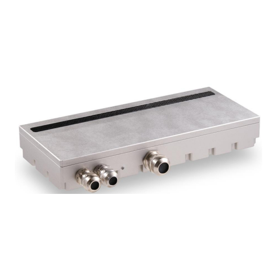
• One 2-pin Lemo connector for power Lemo EXG.0B.302.HLN Mating connector: straight type: FGG.0B.302.CLAD52 • One 4-pin Lemo connector for triggering Lemo EXG.0B.304.HLN Mating connectors: straight type: FGG.0B.304.CLAD52 Trigger Power 5GigE Status connector connector connector Shad-o-Scan 3001/4501 Detector Teledyne DALSA... - Page 11 Shad-o-Scan 3001/4501 User Manual (Draft) Ethernet Connector Ethernet Connection LED Steady orange indicates that an Ethernet connection is successfully established. Data Transmission LED Flashing green indicates that the detector is transmitting or receiving data. Detector Status LED The detector is equipped with an orange/green LED used to display the status of the detector’s operation.
- Page 12 Trigger Input Anode + 100p Trigger Input Cathode - TCMT1600 Shield Pin 1 indicator Description optocoupler collector with 680R +100R series resistor (note 1) optocoupler emitter optocoupler anode with 680R series resistor (note 2) optocoupler cathode Shielding (chassis) Shad-o-Scan 3001/4501 Detector Teledyne DALSA...
- Page 13 Shad-o-Scan 3001/4501 User Manual (Draft) Note 1: maximum voltage across collector and emitter is 70V. Maximum reverse voltage (between emitter and collector) is 6V. Note 2: maximum reverse voltage across cathode and anode is 6V. Teledyne DALSA...
-
Page 14: Setting Up The Detector
Scan detector. A NIC with Jumbo packet support up to 9014 bytes is required to receive streaming video, preferably with a PCI Express slot. Teledyne DALSA advises to use the 5G adapter Network Interface Card (NIC) which is a low cost but high performance and reliable adapter with a PCI Express slot. -
Page 15: Software Installation
Obtain software Website Visit the Teledyne DALSA website to download the latest free version of the Sapera LT SDK, including the CamExpert image viewer: http://www.teledynedalsa.com/imaging/products/software/sapera/lt/download/ The download is free after filling out the on-line registration form. Make sure to select “Full SDK”... -
Page 16: Optimizing Settings
Obviously, when the packet rate is very high (that is, at high transfer rate which is common for 5GigE Vision systems), this represents significant overhead. Most network cards have introduced an interrupt moderation mode where the card waits Shad-o-Scan 3001/4501 Detector Teledyne DALSA... - Page 17 Shad-o-Scan 3001/4501 User Manual (Draft) to have received a certain number of packets over a maximum period of time before issuing the interrupt. This helps reduce the burden on the CPU as it can process multiple packets during the same interruption.
- Page 18 (with a possible impact on the overall system latency). Again, by combining network equipment that can operate at wire-speed and allocating a different network interface port for each detector in the system, we can ensure these pause requests will not be used. Shad-o-Scan 3001/4501 Detector Teledyne DALSA...
-
Page 19: Connecting
IP addresses of Detector Network Interface Card on host system to which the detector is connected The default assigned detector IP address can be modified using the Teledyne DALSA Network Configuration Tool, which is part of the installation package. Teledyne DALSA... -
Page 20: Quick Test With Camexpert
▪ Refer to the Teledyne DALSA Network Imaging package manual if error messages are shown in the Output Messages pane. But first, increase the value of the Interpacket Delay feature available from the GigE Vision TransportLayer Category group in CamExpert. -
Page 21: Acquiring Images
Shad-o-Scan 3001/4501 User Manual (Draft) Acquiring Images The CamExpert software can be started to acquire images. Select the correct device from the Device Selection Menu. The software will display all available device parameters of the detector. The user has the option to either snap an image or to grab continuously. Snapping an image produces a single frame, whereas the grabbing process generates multiple frames by operating in a continuous mode. -
Page 22: Operational Reference
Click on any parameter and a short description is displayed below the Category pane. The same context sensitive help is available by clicking on the button then click on a detector configuration parameter. Click on the button to open the help file for more descriptive information on CamExpert. Shad-o-Scan 3001/4501 Detector Teledyne DALSA... - Page 23 Shad-o-Scan 3001/4501 User Manual (Draft) CamExpert Panes The various areas of the CamExpert tool are described in the summary figure below. GigE Vision device Categories and Parameter features are displayed as per the device’s XML description file. The number of parameters shown is dependent on the View mode selected (Beginner, Expert, Guru –...
- Page 24 CamExpert presents detector features based on their visibility attribute. CamExpert provides quick Visibility level selection (Beginner/Expert/Guru) via controls below each Category Parameter list [ << Less More>> ]. The user can also choose the Visibility level (Beginner/Expert/Guru) from the View - Parameters Options menu. Shad-o-Scan 3001/4501 Detector Teledyne DALSA...
-
Page 25: Camera Information
Shad-o-Scan 3001/4501 User Manual (Draft) Camera Information The following table describes the parameters Display Name as shown in CamExpert and their feature name, accessibility (RO=ReadOnly, RW=Read/Write, WO=WriteOnly) and description. Display Name Feature Description Manufacturer Name DeviceVendorName Displays the device vendor name. - Page 26 User Set Selector Save Configuration UserSetSave feature. The user sets are located on the camera in non-volatile memory The temperature on the Temperature DeviceTemperature processing board in degrees Celcius Shad-o-Scan 3001/4501 Detector Teledyne DALSA...
-
Page 27: Camera Configuration Selection Dialog
Shad-o-Scan 3001/4501 User Manual (Draft) Camera Configuration Selection Dialog CamExpert provides a dialog box which combines the features to select the detector power-up state and for the user to save or load a detector state from memory. Camera (Detector) Power-up Configuration The first drop list selects the detector configuration state to load on power-up (see feature UserSetDefaultSelector). -
Page 28: Sensor Control
Small full well capacitor (default) Horizontal start position for ROI mode; min 0, Horizontal Offset Horizontal Offset max 3072, multiple of 2 Vertical start position for ROI mode; min 1, max Vertical Offset Horizontal Offset 64, multiple of 2 Shad-o-Scan 3001/4501 Detector Teledyne DALSA... -
Page 29: Read-Out Mode
Shad-o-Scan 3001/4501 User Manual (Draft) Horizontal ROI size; min 0, max 3072, multiple Width Width of 2 Height Height RW Vertical ROI size; min 16, max 64, multiple of 2 Read-Out Mode When the ExposureAlignment is set to Synchronous the framerate can be set using the acquisition mode framerate parameter. - Page 30 OffsetY, Width, and Height. The resulting image generated by the device has Width time Height pixels. OffsetX and OffsetY are given with respect to the upper left corner of the image which has the coordinate (0, 0) (see Figure). Shad-o-Scan 3001/4501 Detector Teledyne DALSA...
-
Page 31: Trigger Mode
Shad-o-Scan 3001/4501 User Manual (Draft) Trigger Mode Synchronous Mode In this mode the detector will run continuously on internal timing. No trigger input is required to initiate a frame read-out. The frame rate is determined by the time between successive frame read-outs which can be set by the Exposure or Framerate feature. - Page 32 1/A: Frame rate = trigger frequency 730 FPS 1390 FPS A: integration time 1.36 ms 0.644 ms B: readout time 1.36 ms 0.644 ms C: Frame Blanking interval (A_B) 0.001 ms 0.001 ms Figure timing diagram 'Trigger Mode' Shad-o-Scan 3001/4501 Detector Teledyne DALSA...
-
Page 33: Image Format Control
Shad-o-Scan 3001/4501 User Manual (Draft) Image Format Control The Shad-o-Scan Image Format controls, as shown by CamExpert, group parameters used that give information about the resolution and pixel format. Display Name Feature Acc Description Format of the pixel provided by the device. -
Page 34: Image Processing Control
Off: Disabled On: Enabled FFC Processing FFCActive Shows if FFC processing is enabled and activated Not Active Not Active processing not active Active Active processing active FFC Mode FFCMode Changes Normal Mode for Flat Field Shad-o-Scan 3001/4501 Detector Teledyne DALSA... - Page 35 Shad-o-Scan 3001/4501 User Manual (Draft) Correction Normal Normal Default Flat Field Correction Mode New Dark New Dark Writes New Dark for Flat Field Correction FFC New Dark FFCNewDarkWe Select Weight Weight ight for Dark reference update Dark Map Save FFCNewDarkSa...
- Page 36 FullWell FullWell Invalid InvalidResolutio Invalid Resolution Resolution No Memory NoMemory No Memory No File NoFile No File Invalid Dark InvalidDarkMap Invalid Dark Invalid Gain InvalidGainMap Invalid Gain Undefined UndefinedError Undefined Error Error Not Initialised NotInitialised Shad-o-Scan 3001/4501 Detector Teledyne DALSA...
- Page 37 Shad-o-Scan 3001/4501 User Manual (Draft) Initialised DPC Enable DPCEnable Turns On/Off Defect Pixel Correction On: Enabled Off: Disabled DPC Processing DPCActive Shows if DPC processing is enabled and activated Not Active NotActive processing not active Active Active processing active DPC Error...
- Page 38 Defect pixel reference maps are stored in detector non-volatile memory. These maps contain information on the position of defective (or deviating) pixels, required for Defect Pixel Correction (DPC). These maps are detector-specific, and are generated during Teledyne DALSA factory calibration. Shad-o-Scan 3001/4501 Detector Teledyne DALSA...
- Page 39 Shad-o-Scan 3001/4501 User Manual (Draft) Separate defect pixel maps are available for different Readout- and Full Well modes. These maps are used by the detector to apply DPC on images, before streaming them over the data communications interface. The defect map can be used by the host application to apply corrections for defect pixels in images captured from the detector.
- Page 40 Upload selector in the File Access Control menu has to be set to Customer before opening the File Access Control menu through Upload/Download File. Select Type Miscellaneous in the first drop list and in the second drop list the Defect Map Shad-o-Scan 3001/4501 Detector Teledyne DALSA...
- Page 41 “Teledyne X-Ray Processing Library” functions to apply such corrections, or for the creation and uploading of new correction maps. This library and its API can be downloaded from the Teledyne DALSA FTP server (ftp.teledynedalsa.com) on request. FFC Calculation The pixel value after FFC correction, FFCVal(x,y), is given by the following formula: ��������������...
- Page 42 GainVal(x,y) Pixel value in Gain map UnityGainFactor Value in map representing unity gain, as a power of 2 Offset Fixed value added to prevent noise clipping Shad-o-Scan 3001/4501 Detector Teledyne DALSA...
- Page 43 Shad-o-Scan 3001/4501 User Manual (Draft) File Format The file format of the dark (or gain) maps is as follows: a header indicates the specification of the map, and will be followed by a data block with the dark (or gain) information per pixel.
- Page 44 Shad-o-Scan 3001/4501 Detector Teledyne DALSA...
- Page 45 Shad-o-Scan 3001/4501 User Manual (Draft) How to Create a New Gain Map To use FFC to correct for system specific spatial intensity variations, new Gain maps should be created and uploaded to the detector as part of the factory system calibration routines.
- Page 46 Pressing the Save button after selecting the correct name and location, the detector will start a transfer of the selected dark/gain map file to the host. The download will finish with The file download completed successfully message. Shad-o-Scan 3001/4501 Detector Teledyne DALSA...
-
Page 47: Firmware Update
Shad-o-Scan 3001/4501 User Manual (Draft) Firmware Update Through the CamExpert file access control, a firmware update can be performed. Use the browse button to select a firmware file which has the extension CBF. The filename has the following format: MODELNAMEFWVER.cbf The modelname should be identical as the detector. - Page 48 Shad-o-Scan 3001/4501 Detector Teledyne DALSA...
- Page 49 Shad-o-Scan 3001/4501 User Manual (Draft) Shuttering The Rad-icon Detector does not have a shuttering mechanism built into the detector. The detector can be operated quite normally with a continuous beam x-ray source, however there can be motion blur associated with continuous beam imaging. In the case that pulsed x-ray operation is required, the X-ray pulse must be carefully timed so that x-ray from the pulse are not incident on the detector during readout.
-
Page 50: Mechanical Interface
Mechanical Interface Mechanical Dimensions Shad-o-Scan 3001 Model Shad-o-Scan 3001/4501 Detector Teledyne DALSA... - Page 51 Shad-o-Scan 3001/4501 User Manual (Draft) Shad-o-Scan 4501 Model Teledyne DALSA...
-
Page 52: Revision History
Appendix A Revision History Revision Change Description Revision Date Number Draft release July 6, 2020 First release Sept 15, 2020 Shad-o-Scan 3001/4501 Detector Teledyne DALSA...
Need help?
Do you have a question about the Shad-o-Scan 3001 and is the answer not in the manual?
Questions and answers