Table of Contents
Advertisement
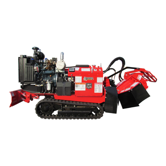
OPERATING & PARTS MANUAL
MODEL 2550
2550
Model No: __________________________
Serial No: __________________________
DEALER:
Name: _____________________________
Address: ___________________________
City/State: __________________________
Phone No: __________________________
Delivery Date: _______________________
Engine Make: _______________________
Serial No: __________________________
Clutch Make: ________________________
Model: ___________ S/N _____________
Copyright 4/21
ATTENTION:
Depending on what replacement parts you are ordering, we will need the following information:
STUMP GRINDER COMPONENTS
ENGINE COMPONENTS
Serial Number
Brand
Model Number of Stump Grinder
Engine Serial Number
Engine Model Number
MANUFACTURED BY BANDIT INDUSTRIES, INC
PHONE:
989
561-2270
(
)
PHONE:
800
952-0178 IN USA
(
)
FAX:
989
561-2273 ~ SALES DEPT.
(
)
FAX:
989
561-2962 ~ PARTS/SERVICE
(
)
WEBSITE:
www.banditchippers.com
6750 Millbrook Rd. • Remus, MI 49340 • 1-989-561-2270
Advertisement
Table of Contents

Related Manuals for Bandit 2550


Summary of Contents for Bandit 2550
- Page 1 Depending on what replacement parts you are ordering, we will need the following information: STUMP GRINDER COMPONENTS ENGINE COMPONENTS Serial Number Brand Model Number of Stump Grinder Engine Serial Number Engine Model Number MANUFACTURED BY BANDIT INDUSTRIES, INC PHONE: 561-2270 PHONE: 952-0178 IN USA FAX: 561-2273 ~ SALES DEPT. FAX:...
- Page 2 CALIFORNIA PROPOSITION 65 WARNING ADVERTENCIA Breathing diesel engine Respirar gases de escape de exhaust exposes you to motores diesel expone chemicals known to the quÍmicos conocidos por el estado State of California to cause de California como causales de cancer and birth defects or cáncer y defectos congénitos u other reproductive harm.
- Page 3 11. _____ The customer has received instruction and fully understands that warranty will not apply if the machine is operated with replacement parts or equipment not manufactured or recommended by Bandit Industries, Inc. 12. _____ The customer has received, been advised, and understands the manuals, and the Safety/Service video supplied with the grinder.
- Page 4 Copyright 4/17 FORM #Q-112 DATE PURCHASE: ______________________ TO BE RETURNED AFTER THIRTY (30) DAYS OF OPERATION MODEL: ________________________________ SERIAL NUMBER: _______________________ Please return to: Customer Data Department 6750 Millbrook Road DEALER NAME: ________________________ Remus, MI 49340 _______________________________________ Phone: (800) 952-0178 in USA Phone: (989) 561-2270 Fax: (989) 561-2273...
-
Page 5: Table Of Contents
MODELS 2550/2550T TABLE OF CONTENTS TABLE OF CONTENTS PAGE INTRODUCTION & WARRANTY ............2 SERIAL NUMBER LOCATIONS ............6 SAFETY PROCEDURES................ 7 EQUIPMENT SPECIFICATIONS ............12 DECALS ....................13 CONTROLS ..................... 17 MACHINE OPERATION ................. 33 TRANSPORTATION PROCEDURES ............ 36 MAINTENANCE .................. -
Page 6: Introduction & Warranty
NOTICE The producer of this Bandit product reserves the right to make any modifi cations or revisions to the design or specifi cations of its machine without advance notice. The producer also reserves the right to change machine and part prices as needed without advance notice. - Page 7 The warranty validation form must be completed and submitted to Bandit Industries within 10 business days of the purchase of your Bandit machine. Any and all warranty is NULL AND VOID if the Warranty Validation Form is not returned within 10 business days of the original purchase of the machine.
- Page 8 This warranty will not apply if the Bandit product is not operated with replacement parts or equipment not manufactured or recommended by Bandit Industries, Inc. This warranty will not apply if the Bandit product is not operated in a manner recommended by the manufacturer. The following examples would void the warranty: 1.
- Page 9 Manufacturer or our authorized dealer. If an RMA is given to return the failed parts, they must be returned within 10 business days to the respective vendor or Bandit Industries depending on the instructions given. The new parts must be installed and work be complete within 10 business from receiving the parts to receive credit.
-
Page 10: Serial Number Locations
MODELS 2550/2550T SERIAL NUMBER LOCATIONS TYPICAL SERIAL NUMBER AND/OR WORK ORDER NUMBER LOCATIONS NOTICE 1. Side of control box 2. W/O # on pivot mount plate The engine information is located on the engine block. The clutch information is located on the clutch plate (if equipped). -
Page 11: Safety Procedures
You may obtain additional copies of this Torn or loose clothing is more likely to get caught manual from your Bandit Dealer. in moving machinery parts. Keep such items as long Before operating machine, you must have all hair, shirt sleeves, and shirt tails properly contained. - Page 12 2” (50mm) Most of the nuts used on the Bandit Grinder are from the top of the tank for gasoline engines. self locking. After a nut or bolt has been removed...
- Page 13 MODELS 2550/2550T SAFETY PROCEDURES SAFETY PROCEDURES DANGER DANGER DO NOT start the engine with the clutch or cutter Never grind materials that might contain wires, wheel engaged. stones, nails, or other metal objects which may damage NOTICE the teeth and become dangerous projectiles. Remove all rocks and stones from stump grinding area.
- Page 14 MODELS 2550/2550T SAFETY PROCEDURES SAFETY PROCEDURES WARNING WARNING CLEAN MACHINE OF ALL DEBRIS! DO NOT Sparks can occur if cutter teeth strike rocks, leave this machine unattended until all potential fi re metal, or other hard objects. debris is removed, no fi re or smoldering exists, and DO NOT use in high or very high fi re hazard hot spots are cold.
- Page 15 MODELS 2550/2550T SAFETY PROCEDURES SAFETY PROCEDURES IF MACHINE IS EQUIPPED WITH A SELF PROPELLED UNDERCARRIAGE Machines equipped with undercarriage tracks are shipped with a manual from the track manufacturer. Refer to it for service, operation, and safety information. WARNING Do not attempt to operate the machine on an ascending or descending slope of more than 25° or 46% or a side slope of more than 17°...
-
Page 16: Equipment Specifications
MODELS 2550/2550T EQUIPMENT SPECIFICATIONS EQUIPMENT SPECIFICATIONS Approximate Dimensions & Weights (Dimensions & weights will vary depending on optional equipment) MODEL 2550 MODEL 2550T Manual 72” (1.8 m) Manual 72” (1.8 m) Height Height Remote 55” (1.4 m) Remote 55” (1.4 m) Length 122”... - Page 17 MODELS 2550/2550T DECALS DECAL LOCATIONS DANGER DO NOT go near the rotating cutter wheel for any reason. DO NOT go near the cutter wheel while the engine is running or the cutter wheel is coasting to a stop. Contact with a rotating cutter wheel will result in serious bodily injury or death.
- Page 18 MODELS 2550/2550T DECALS DECAL LOCATIONS Decal locations may vary, these are general locations. 1,5,6,16 39,51 24,25,43 46,47,53, 14,37, 57,58 45,59 1,15 2,38,41 12,29 1,6,54 1,9, 21,32,34, 35,36,49, 3,7,10,11, 50,55,56 21,23,32, 3,7,10,11, 33,35,36 26,27,33,42 40,44 4,22, 17,18,19, 8,49 31,41, 31,48 53,54,55...
- Page 19 INST-151 Brake Release Procedure Basic Safety Decal Kit - 61 900-8900-37 English Turn Ball Valve...To Release INST-152 Brakes Bandit Model 2550 Logo 62 900-8901-97 Decal Kit INST-153 Brake Release Hand Pump Bandit Model 2550T Logo INST-161 Turn...To Free Brakes 63 900-8902-81...
-
Page 20: Decals
DECALS DECALS Decals located on your Bandit equipment contain useful information to assist you in operating your equipment safely. Some of the decals on your machine and their location are shown in this section. It is very important that all decals remain in place and in good condition on your machine. Please follow the care and instructions given below: You should use soap and water to keep your decals clean. - Page 21 MODELS 2550/2550T CONTROLS MACHINE ORIENTATION REFERENCE R I G Bandit Copyright 4/21...
-
Page 22: Controls
MODELS 2550/2550T CONTROLS EMERGENCY STOP (E-STOP) DANGER Avoid moving parts. Keep hands, feet, and clothing away from power driven parts. Keep all guards and shields in place and properly secured. DANGER DO NOT go near the rotating cutter wheel for any reason. DO NOT go near the cutter wheel while the engine is running or the cutter wheel is coasting to a stop. - Page 23 ENGINE OPERATING SPEEDS NOTICE Refer to the Completion/Check Sheet, that is shipped with the machine for the correct engine rpm. If needed, contact your local dealer or Bandit Industries. Some Current Engine Types Maximum RPM Kubota WG1605G - 49.6 Hp 2700 Kubota D1803-CR - 49.6 Hp...
- Page 24 MODELS 2550/2550T CONTROLS 2550 CONTROLS - MANUAL Bandit Copyright 4/21...
- Page 25 MODELS 2550/2550T CONTROLS CONTROL OPERATING PROCEDURES MANUAL 1. Swing Speed Control: The swing speed controls the rate the cutter wheel passes through the stump. To decrease the swing speed, turn the control knob clockwise. 2. Travel Speed Control: The travel speed controls the rate the machine approaches the stump. To decrease the travel speed, turn the control knob clockwise.
- Page 26 MODELS 2550/2550T CONTROLS 2550 CONTROLS - SWING OUT Bandit Copyright 4/21...
- Page 27 MODELS 2550/2550T CONTROLS CONTROL OPERATING PROCEDURES SWING OUT 1. Swing Out Lock Pin: Lock the swing out lock pin into the operating position or the transport position. 2. Cutter Wheel On / Off Switch: Before engaging or disengaging the cutter wheel, make sure the engine is at an idle.
- Page 28 MODELS 2550/2550T CONTROLS 2550 CONTROLS - REMOTE Bandit Copyright 4/21...
- Page 29 MODELS 2550/2550T CONTROLS CONTROL OPERATING PROCEDURES REMOTE 1. Ignition Switch: Location varies with different engine options. 2. Cutter Wheel On / Off Switch: Before engaging or disengaging the cutter wheel, make sure the engine is at an idle. To turn the cutter wheel on, push the switch up. To turn the cutter wheel off, push the switch down.
- Page 30 MODELS 2550/2550T CONTROLS 2550 TRACK CONTROLS - MANUAL Bandit Copyright 4/21...
- Page 31 MODELS 2550/2550T CONTROLS CONTROL OPERATING PROCEDURES MANUAL 1. Travel Speed Control: The travel speed controls the rate the machine approaches the stump. To decrease the travel speed, turn the control knob clockwise. 2. Swing Speed Control: The swing speed controls the rate the cutter wheel passes through the stump.
- Page 32 MODELS 2550/2550T CONTROLS 2550 TRACK CONTROLS - SWING OUT Bandit Copyright 4/21...
- Page 33 MODELS 2550/2550T CONTROLS CONTROL OPERATING PROCEDURES SWING OUT 1. Travel Speed Control: The travel speed controls the rate the machine approaches the stump. To decrease the travel speed, turn the control knob clockwise. 2. Swing Speed Control: The swing speed controls the rate the cutter wheel passes through the stump.
- Page 34 MODELS 2550/2550T CONTROLS 2550 TRACK CONTROLS - REMOTE Bandit Copyright 4/21...
- Page 35 MODELS 2550/2550T CONTROLS CONTROL OPERATING PROCEDURES REMOTE 1. Power Display: Displays engine information: Temperature, RPMs, Tach / Hour Meter, etc. 2. Ignition Switch: Location varies with different engine options. 3. Link Light: If the transmitter is linked to the machine the link light will be on.
- Page 36 5. “Bandit” Lever Lock Cable Throttle System (if equipped): The Bandit throttle system has (2) positions, HIGH and LOW. Engine R.P.M. is controlled by moving the lever from one position to the other.
-
Page 37: Machine Operation
MODELS 2550/2550T MACHINE OPERATION MACHINE OPERATION DANGER WARNING Do not start to grind a stump unless you are Wear all personal protective equipment per ANSI, completely sure there are not any utility lines in OSHA and manuals. the area above or below the ground level where NOTICE you are grinding. - Page 38 MODELS 2550/2550T MACHINE OPERATION CUTTING AREA DANGER For optimum performance, the stump should be cut with the portion of the cutter wheel shown below. NEVER UNDERCUT THE STUMP. Undercutting the stump may cause severe kickback, vibration and component damage. NEVER CUT THE STUMP FROM THE TOP. The cutter wheel will throw debris up and toward the operator, instead of down and under the machine.
- Page 39 MODELS 2550/2550T MACHINE OPERATION MOVING A MACHINE WITHOUT POWER (MODEL 2550) NOTICE Use this procedure only when the machine will not start or run to help prevent damage to the hydraulic system. With the key in the “off” position and in your possession, follow the steps below: 1.
-
Page 40: Transportation Procedures
MODELS 2550/2550T TRANSPORTATION PROCEDURES TRANSPORTATION PROCEDURES WARNING BEFORE TRANSPORTING THE MACHINE, INSPECT AND CONFIRM THE FOLLOWING STEPS: The trailer must have a cargo weight rating capacity for the weight of the stump grinder. The combined weight of the trailer and the stump grinder can not exceed the load capacity of the tires, axles, hitch coupler system or the GVWR (Gross Vehicle Weight Rating) of the trailer. - Page 41 MODELS 2550/2550T TRANSPORTATION PROCEDURES LOADING & UNLOADING WARNING BEFORE LOADING OR UNLOADING THE MACHINE, INSPECT AND CONFIRM THE FOLLOWING STEPS: When loading or unloading the self-propelled machine on the trailer, use care and caution. The maneuvering of the equipment must be slow, smooth, and intentional, not fast and jerky.
- Page 42 MODELS 2550/2550T MAINTENANCE MACHINE ORIENTATION REFERENCE R I G Bandit Copyright 4/21...
-
Page 43: Maintenance
Failure to properly break-in your engine may result in poor bearing and piston ring surfaces. NOTICE The Bandit has only been run for a short time to test proper hydraulic pressures, possible leaks, etc. The fuel tank will be empty. Fuel is provided through a small auxiliary tank for testing. This immensely helps maintain safety in our manufacturing facility and while shipping. - Page 44 12. Check the fuel level: 18. Inspect axle dust caps (Model 2550): Check the fuel level, running out and repriming is Inspect axle dust caps and replace if damaged or time consuming. Do not over fill, and you must leave leaking.
- Page 45 (i.e. cutter wheel guard, control box will attract dirt. doors, etc.). 2. Grease steering axle pivot bushings (Model 2550): 7. Check the cutter wheel hydraulic motor coupler: Grease steering axle pivot bushings with 1 to 2 shots Remove the cover plate over the cutter wheel of EP-2 Lithium type grease.
- Page 46 16. Check air cleaner, precleaner, and vacuator valve. Clean as necessary. 17. Check the condition of the tires. Fill as needed (2550). 18. Inspect and replace any axle dust caps that are damaged or leaking (Model 2550). 19. Check track tension and condition of the tracks (Model 2550T).
- Page 47 OK REPAIRED Inspect and clean steering wheel hub bearings, cups, and seals. Grease steering wheel hub bearings. Replace seals if ever removed (Model 2550 w/ 2 Wheel Drive) Drain and clean the fuel tank. Change hydraulic oil and flush the hydraulic tank.
- Page 48 MODELS 2550/2550T MAINTENANCE LUBRICATION CHART - 2550 CHECK # DESCRIPTION DAY WEEK MONTH PROCEDURE 1 Cutter Wheel Arm Pivot Bushings 1 - 2 shots of grease - wipe off excess 2 Swing Pivot Ass’y Bushings 1 - 2 shots of grease - wipe off excess...
- Page 49 MODELS 2550/2550T MAINTENANCE LUBRICATION CHART - 2550 Use as a reference only, locations may vary depending on options or component manufacturer. NOTICE Lubrication point instructions are described on the machine, in the Lubrication & Coolant Section and Maintenance Section of this manual, or component manufacturer’s manual.
- Page 50 MODELS 2550/2550T MAINTENANCE LUBRICATION CHART - 2550T CHECK # DESCRIPTION DAY WEEK MONTH PROCEDURE 1 Cutter Wheel Arm Pivot Bushings 1 - 2 shots of grease - wipe off excess 2 Swing Pivot Ass’y Bushings 1 - 2 shots of grease - wipe off excess...
- Page 51 MODELS 2550/2550T MAINTENANCE LUBRICATION CHART - 2550T Use as a reference only, locations may vary depending on options or component manufacturer. NOTICE Lubrication point instructions are described on the machine, in the Lubrication & Coolant Section and Maintenance Section of this manual, or component manufacturer’s manual.
- Page 52 PAINT CARE & WINDOW WASHING PAINT CARE To help keep up the appearance of your Bandit equipment and reduce the possibility of surface rust follow these steps: 1. The machine should be washed by hand with water for the fi rst 30 days when the paint is fresh. Afterwards, the machine should be washed on a regular basis with an automotive wash soap (not degreaser) and then rinsed thoroughly.
- Page 53 MODELS 2550/2550T MAINTENANCE CUTTER WHEEL MAINTENANCE DANGER DANGER Before attempting any type of maintenance, DO NOT operate machine with extremely worn or disengage clutch or cutter wheel engagement, wait broken teeth. for the cutter wheel to come to a complete stop,...
- Page 54 MODELS 2550/2550T MAINTENANCE CUTTER WHEEL MOTOR COUPLER DANGER Before attempting any type of maintenance, disengage clutch or cutter wheel engagement, wait for the cutter wheel to come to a complete stop, position and lock the cutter wheel in the transport position, turn off engine, remove the ignition key, make sure the ignition key is in your possession, install the cutter wheel lock pin, wait 2 minutes then disconnect the battery.
- Page 55 MODELS 2550/2550T MAINTENANCE CUTTER WHEEL MOTOR COUPLER Stub Shaft Stub Shaft Brace Cutter Wheel Hub Coupler Removal Hole Cutter Wheel Cutter Wheel Motor Coupler Cutter Wheel Motor Shaft Bandit Copyright 4/21...
- Page 56 Allowable Tolerances on mating parts Allowable Tolerances on mating parts TLK 130/450 (1 3/4”) TLK 450 (2 1/4”) Models: 2250, 2550R, 2550, 2600, 2650 Models: 2700, 2890, 2900 Shaft Tolerance 1.750” -.002 Shaft Tolerance 2.250” -.002 Hub Tolerance 2.953”...
- Page 57 MODELS 2550/2550T MAINTENANCE TRACK ADJUSTMENT DANGER Before attempting any type of maintenance disengage clutch, turn off engine, wait for the cutter wheel to come to a complete stop, install the cutter wheel lock pin, place the cutter wheel on the ground, disconnect battery, and make sure the ignition key is in your possession.
- Page 58 MODELS 2550/2550T MAINTENANCE TROUBLESHOOTING PROBLEM POSSIBLE CAUSE SOLUTION Loose ground cable. Clean and tighten. Loose hot cable. Clean and tighten. Dead battery. Recharge or replace. Engine will not start. (See Make sure the ignition switch is off, Cutter wheel was engaged before the Engine Mfg.
-
Page 59: Hydraulics
Failure to plug ports will allow debris to enter components which will void warranty. The Bandit is equipped with a very efficient, simple hydraulic system. Each component is capable of withstanding a specified PSI (bar) and still operate for a very long time. - Page 60 Based on the varying temperatures of the area When choosing a hydraulic fluid - these maximum where Bandit equipment is used, and the high and minimum specifications must be met: demand and loads placed on this equipment, Bandit has filled each hydraulic system with Petro-Canada’s...
- Page 61 MODELS 2550/2550T HYDRAULICS HYDRAULICS - 2550 TYPICAL HYDRAULIC RELIEF PRESSURE SETTINGS TYPICAL HYDRAULIC FLOWS AND RPM SETTINGS (Approximate, For Reference Only, Engine At Full RPM) 2550 with MANUAL Control Valves Cutter Cutter Wheel Auxiliary Cutter Wheel PSI Engine Wheel Pump GPM...
- Page 62 MODELS 2550/2550T HYDRAULICS HYDRAULICS - 2550 TRACK TYPICAL HYDRAULIC RELIEF PRESSURE SETTINGS TYPICAL HYDRAULIC FLOWS AND RPM SETTINGS (Approximate, For Reference Only, Engine At Full RPM) 2550 TRACK with REMOTE Control Valves Cutter Cutter Wheel Auxiliary Cutter Wheel PSI Engine...
- Page 63 MODELS 2550/2550T HYDRAULICS HYDRAULICS - 2550 TRACK TYPICAL HYDRAULIC RELIEF PRESSURE SETTINGS TYPICAL HYDRAULIC FLOWS AND RPM SETTINGS (Approximate, For Reference Only, Engine At Full RPM) 2550 TRACK with MANUAL Control Valves Cutter Cutter Wheel Auxiliary Cutter Wheel PSI Engine...
- Page 64 MODELS 2550/2550T HYDRAULICS CHECKING HYDRAULIC PRESSURE The relief valve is typically located internally in the valve bank. Do not adjust the relief valves above the specified psi (bar). The relief valve system is a simple spring tension design but small pieces of debris can stick the valve partially open which weakens the hydraulic power.
- Page 65 MODELS 2550/2550T HYDRAULICS CHECKING HYDRAULIC FUNCTION PRESSURE FIGURE 1 Swing Out Controls FIGURE 2 Model 2550 Remote Control Cutter Wheel Main Test Port Main Test Port Lift Down Relief Relief Relief FIGURE 3 Model 2550T Remote Control FIGURE 4 Test Port...
- Page 66 MODELS 2550/2550T HYDRAULICS HYDRAULIC SYSTEM TROUBLESHOOTING Before attempting any type of maintenance disengage clutch, turn off engine, wait for the cutter wheel to come to a complete stop, install the cutter wheel lock pin, place the cutter wheel on the ground, disconnect battery, and make sure the ignition key is in your possession.
- Page 67 1. Follow all pre-maintenance shut down procedures. 2. Remove and clean the fitting shown in above picture. 3. Reassemble the fitting as shown above. 4. If this does not solve the problem contact your local dealer or Bandit Industries, Inc. Bandit Copyright 4/21...
-
Page 68: Electrical
MODELS 2550/2550T ELECTRICAL ELECTRICAL - MACHINE HARNESSES 2550 Machine Harness for Kubota Diesel 49 Hp - Manual ..............203-8000-50 Machine Harness for Kubota Diesel 49 Hp - Swing Out.............. 203-8000-63 Machine Harness for Kubota Diesel 49 Hp - Remote..............203-8000-65 Machine Harness for Kubota Diesel 49 Hp with Fans - Remote .......... -
Page 69: Replacement Parts
Some of the components shown in this section are for optional equipment and may not apply to every machine. NOTICE Bandit Industries Inc. reserves the right to make changes in models, size, design, installations and applications on any part without notification. MACHINE ORIENTATION REFERENCE... - Page 70 MODELS 2550/2550T CUTTER WHEEL ARM COMPONENTS NOTICE Parts may not be exactly as shown. Bandit Copyright 4/21...
-
Page 71: Cutter Wheel Arm Components
MODELS 2550/2550T CUTTER WHEEL ARM COMPONENTS Part Number Description Part Number Description 203-2000-35 Chip Pan 13 900-3958-80 Swing Cylinder 203-3002-97 Split Chip Curtain - Front 14 900-3934-20 Cylinder Pin - 1” x 2 7/8” 203-3002-98 Split Chip Curtain - Middle 15 900-4901-47 3/4”... -
Page 72: Cutter Wheel Components
MODELS 2550/2550T CUTTER WHEEL COMPONENTS Part Number Description Part Number Description 900-4919-83 14mm x 60mm Hex Head Bolt 203-3002-56 Cutter Wheel Hub (Start 4/14) Manifold Block for Cutter 203-3000-74 Cutter Wheel Hub (Pre 4/14) 900-3955-99 Wheel Motor Cutter Wheel Assembly... - Page 73 MODELS 2550/2550T CUTTER WHEEL COMPONENTS CUTTER WHEEL BAR Part Number Description 203-2001-37 Cutter Wheel Bar Assembly 203-3004-96 Cutter Wheel Bar Linkage Shoulder Bolt - 900-4918-22 1/2” x 3/8”-16NC x 1/2” 900-4906-60 3/8”-16NC Lock Nut NOTICE Nuts, bolts, washers, and all other components can be ordered by physical description.
- Page 74 MODELS 2550/2550T CUTTER WHEEL COMPONENTS BANDIT CUTTER WHEEL WITH GREEN TEETH Part Number Description Part Number Description Green Teeth Cutter Wheel 900-9907-87 Straight Pocket 203-1000-63 Assembly (Includes 6) 900-9907-86 Angle Pocket 203-3001-05 Bandit Cutter Wheel Only Green Wheel Tooth Kit...
- Page 75 MODELS 2550/2550T CUTTER WHEEL COMPONENTS NEW RIVER “REVOLUTION” CUTTER WHEEL & TEETH Part Number Description Part Number Description New River “Revolution” Cutter 900-9912-24 Lead Tooth (Short) for Hex Teeth 900-9912-86 Wheel Assembly - Hex Teeth Lead Tooth (Short) for Square 900-9909-96 New River “Revolution”...
- Page 76 MODELS 2550/2550T FRAME COMPONENTS MODEL 2550T NOTICE Parts may not be exactly as shown. Bandit Copyright 4/21...
-
Page 77: Frame Components
MODELS 2550/2550T FRAME COMPONENTS MODEL 2550T Part Number Description Part Number Description 900-5916-78 Rubber Track - No Tread Split Bushing - 21 900-1916-28 900-5913-05 Rubber Track - With Tread 1” OD x 3/4” x 1/2” 22 203-2000-84 Swing Out Bolt-On Mount... - Page 78 MODELS 2550/2550T FRAME COMPONENTS MODEL 2550 NOTICE Parts may not be exactly as shown. Bandit Copyright 4/21...
- Page 79 MODELS 2550/2550T FRAME COMPONENTS MODEL 2550 Part Number Description Part Number Description 900-4913-38 1”-8NC x 5 1/2” Hex Head Bolt 22 900-9910-28 Manual Holder 18” x 8.50” - 10” Tire & White, 23 203-2000-53 Manual Holder Mount 900-5909-22 5-Bolt Rim (Specify Left or Right)
- Page 80 MODELS 2550/2550T STEERING COMPONENTS 20 15 NOTICE Parts may not be exactly as shown. Bandit Copyright 4/21...
-
Page 81: Steering Components
MODELS 2550/2550T STEERING COMPONENTS Part Number Description Part Number Description 900-4909-42 1/2”-20NF Lug Nut Split Bushing - 13 900-1919-25 1 1/4” OD x 1” ID x 1/2” 18” x 8.50” - 10” Tire & White, 900-5909-22 5-Bolt Rim (Specify Left or Right) 1”-8NC x 5 1/2”... -
Page 82: Tank Components
1/4” NPTF to 1/4” Hose Barb 203-2001-06 35Hp, Kohler 38Hp, Kubota 44.2Hp 900-3943-22 3/16” NPTF to 3/16” Hose Barb 203-1000-41 Fuel Tank Ass’y - 2550 900-3943-21 1/4” NPTF to 3/16” NPTF Bushing 203-2001-07 Fuel Tank Weldment - 2550 Suction Drop Pipe Ass’y w/o 203-1000-55 Fuel Tank Ass’y - 2550T... - Page 83 MODELS 2550/2550T TANK COMPONENTS (Pre 5/15) Part Number Description Part Number Description 900-3922-60 Magnetic Drain Plug In-Tank Return Filter Assembly 900-3951-31 (Start 11/12) Fuel & Hydraulic Tank 203-2000-30 Assembly In-Tank Return Filter Assembly 900-3938-23 (Pre 11/12) Glass Sight Gauge for...
-
Page 84: Control Box Components
MODELS 2550/2550T CONTROL BOX COMPONENTS MODEL 2550 PART NUMBERS Part Number Description Part Number Description Control Box - Manual No Swing 203-3004-68 Swing Out Hole Cover 203-1000-58 203-3002-26 Swing Out Hose Guard 203-1000-59 Control Box - Manual Swing Out 900-2931-47... - Page 85 Tach / Hour Hole Plug 203-2000-41 Out Controls* 900-2919-33 Tach Hour Meter Control Box Assembly for 904-0002-51 Tach Hour Meter♦ 203-2000-50 Remote Controls (2550)* 998-3704-36 LOFA Panel Control Box Assembly for 14603 Key Only 203-2000-81 Remote Controls (2550T)* Extension Harness for LOFA...
-
Page 86: Swing Out Components
MODELS 2550/2550T SWING OUT COMPONENTS Part Number Description Part Number Description Swing Out Assembly 203-3001-86 Limit Switch Engage 203-1000-21 (Includes 1 - 7, 11, & 14 -16) 203-2000-42 Spring Pin Assembly 203-2000-39 Swing Out Weldment 900-7900-96 Rubber Cap for Spring Lock... -
Page 87: Curtain Swing Out Components
Part Number Description 203-3005-29 Chip Curtian - 2550 900-4913-46 Chip Curtian Washer 203-3005-12 Chip Curtian - 2550T Swing Out Curtain Ass’y - 2550 203-1000-72 (Includes 1-6) 203-2001-51 Curtain Arm Swing Out Curtain Ass’y - 2550T 203-2001-50 Bolt On Curtain Mount... -
Page 88: Grading Blade Components
Part Number Description Part Number Description Grading Blade Mount - Model Grading Blade Pin Assembly 203-2000-29 991-1000-66 2550 (Includes 13) (Includes 6) Grading Blade Mount - Model 900-4900-06 Grading Blade Pin Grease Zerk 203-2000-83 2550T (Includes 13) Split Bushing - 900-1916-28 Grading Blade Lower Arm 1”... -
Page 89: Remote Control Components
MODELS 2550/2550T REMOTE CONTROL COMPONENTS Part Number Description Part Number Description 900-2932-35 Remote 900-2926-44 Tether - 2550 900-2931-75 Transmitter 900-2928-82 Tether - 2550T 900-2929-09 Antenna 900-2908-63 Cap for Tether Jack 999-8002-72 Loomed Antenna Cable NOTICE Parts may not be exactly as shown. - Page 90 MODELS 2550/2550T HYDRAULIC DIAGRAM 2550 - MANUAL / SWING OUT CONTROLS NOTICE Parts may not be exactly as shown. Bandit Copyright 4/21...
-
Page 91: Hydraulic Diagram
MODELS 2550/2550T HYDRAULIC DIAGRAM 2550 - MANUAL / SWING OUT CONTROLS Part Number Description Part Number Description See pp 78-79 Hydraulic Tank 11 900-3952-11 Oil Cooler 900-3951-31 In Tank Filter (Start 11/12) 12 900-3947-20 Braking Motor 900-3951-32 Filter Element Only (Start 11/12) - Page 92 MODELS 2550/2550T HYDRAULIC DIAGRAM 2550 - REMOTE CONTROLS NOTICE Parts may not be exactly as shown. Bandit Copyright 4/21...
- Page 93 MODELS 2550/2550T HYDRAULIC DIAGRAM 2550 - REMOTE CONTROLS Part Number Description Part Number Description See pp 78-79 Hydraulic Tank 10 900-3952-11 Oil Cooler 900-3951-31 In Tank Filter (Start 11/12) 11 900-3947-20 Braking Motor 900-3951-32 Filter Element Only (Start 11/12) 12 900-3947-21...
- Page 94 MODELS 2550/2550T HYDRAULIC DIAGRAM 2550T - MANUAL / SWING OUT CONTROLS NOTICE Parts may not be exactly as shown. Bandit Copyright 4/21...
- Page 95 MODELS 2550/2550T HYDRAULIC DIAGRAM 2550T - MANUAL / SWING OUT CONTROLS Part Number Description Part Number Description See pp 78-79 Hydraulic Tank 900-3956-11 Oil Cooler 900-3951-31 In Tank Filter (Start 11/12) 10 900-3924-30 Swing Speed Adjust 900-3951-32 Filter Element Only (Start 11/12)
- Page 96 MODELS 2550/2550T HYDRAULIC DIAGRAM 2550T - REMOTE CONTROLS NOTICE Parts may not be exactly as shown. Bandit Copyright 4/21...
- Page 97 MODELS 2550/2550T HYDRAULIC DIAGRAM 2550T - REMOTE CONTROLS Part Number Description Part Number Description See pp 78-79 Hydraulic Tank 900-3960-10 Remote Manifold Assembly 900-3951-31 In Tank Filter (Start 11/12) Swing/Travel Control (NV-1, 900-3945-71 NV2) 900-3951-32 Filter Element Only (Start 11/12)
-
Page 98: Service Record
MODELS 2550/2550T SERVICE RECORD SERVICE RECORD DATE DESCRIPTION AMOUNT Bandit Copyright 4/21...
Need help?
Do you have a question about the 2550 and is the answer not in the manual?
Questions and answers