Table of Contents
Advertisement
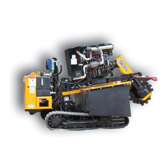
OPERATING & PARTS MANUAL
MODEL SG-75
SG-75
Model No: __________________________
Serial No: __________________________
DEALER:
Name: _____________________________
Address: ___________________________
City/State: __________________________
Phone No: __________________________
Delivery Date: _______________________
Engine Make: _______________________
Serial No: __________________________
Clutch Make: ________________________
Model: ___________ S/N _____________
Copyright 11/19
ATTENTION:
Depending on what replacement parts you are ordering, we will need the following information:
STUMP GRINDER COMPONENTS
ENGINE COMPONENTS
Serial Number
Brand
Model Number of Stump Grinder
Engine Serial Number
Engine Model Number
MANUFACTURED BY BANDIT INDUSTRIES, INC
PHONE:
989
561-2270
(
)
PHONE:
800
952-0178 IN USA
(
)
FAX:
989
561-2273 ~ SALES DEPT.
(
)
FAX:
989
561-2962 ~ PARTS/SERVICE
(
)
WEBSITE:
www.banditchippers.com
6750 Millbrook Rd. • Remus, MI 49340 • 1-989-561-2270
Advertisement
Table of Contents

Related Manuals for Bandit SG-75


Summary of Contents for Bandit SG-75
- Page 1 Depending on what replacement parts you are ordering, we will need the following information: STUMP GRINDER COMPONENTS ENGINE COMPONENTS Serial Number Brand Model Number of Stump Grinder Engine Serial Number Engine Model Number MANUFACTURED BY BANDIT INDUSTRIES, INC PHONE: 561-2270 PHONE: 952-0178 IN USA FAX: 561-2273 ~ SALES DEPT. FAX:...
- Page 2 CALIFORNIA PROPOSITION 65 WARNING ADVERTENCIA Breathing diesel engine Respirar gases de escape de exhaust exposes you to motores diesel expone chemicals known to the quÍmicos conocidos por el estado State of California to cause de California como causales de cancer and birth defects or cáncer y defectos congénitos u other reproductive harm.
- Page 3 11. _____ The customer has received instruction and fully understands that warranty will not apply if the machine is operated with replacement parts or equipment not manufactured or recommended by Bandit Industries, Inc. 12. _____ The customer has received, been advised, and understands the manuals, and the Safety/Service video supplied with the grinder.
- Page 4 Copyright 2/17 FORM #Q-112 DATE PURCHASE: ______________________ TO BE RETURNED AFTER THIRTY (30) DAYS OF OPERATION MODEL: ________________________________ SERIAL NUMBER: _______________________ Please return to: Customer Data Department 6750 Millbrook Road DEALER NAME: ________________________ Remus, MI 49340 _______________________________________ Phone: (800) 952-0178 in USA Phone: (989) 561-2270 Fax: (989) 561-2273...
-
Page 5: Table Of Contents
MODEL SG-75 TABLE OF CONTENTS TABLE OF CONTENTS PAGE INTRODUCTION & WARRANTY ............2 SERIAL NUMBER LOCATIONS ............6 SAFETY PROCEDURES ................ 7 EQUIPMENT SPECIFICATIONS ............12 DECALS ....................13 CONTROLS ..................... 16 MACHINE OPERATION ................. 22 TRANSPORTATION PROCEDURES ............ 24 MAINTENANCE .................. -
Page 6: Introduction & Warranty
The purpose of this manual is to provide the user with specifi cations and procedures for the operation, maintenance and repair of this BANDIT product. As with any piece of equipment, safety should always be a constant thought while the machine is being operated, serviced or stored. -
Page 8: Serial Number Locations
MODEL SG-75 SERIAL NUMBER LOCATIONS TYPICAL SERIAL NUMBER AND/OR WORK ORDER NUMBER LOCATIONS NOTICE 1. Serial Number behind pump on left side. The engine information is located on the 2. Work Order Number on track frame. engine block. Bandit Copyright 8/19... -
Page 9: Safety Procedures
You may obtain additional copies of this Torn or loose clothing is more likely to get caught manual from your Bandit Dealer. in moving machinery parts. Keep such items as long Before operating machine, you must have all hair, shirt sleeves, and shirt tails properly contained. - Page 10 t. from top of tank for diesel engines and 2” (50mm) Most of the nuts used on the Bandit Grinder are from the top of the tank for gasoline engines. self locking. After a nut or bolt has been removed To obtain the most from your machine, for the least fi ...
- Page 11 MODEL SG-75 SAFETY PROCEDURES SAFETY PROCEDURES DANGER DANGER Do not start the engine with cutter wheel engaged. Never grind materials that might contain wires, stones, nails, or other metal objects which may damage NOTICE the teeth and become dangerous projectiles. Remove Do not attempt to start the engine, engage all rocks and stones from stump grinding area.
- Page 12 MODEL SG-75 SAFETY PROCEDURES SAFETY PROCEDURES WARNING WARNING Sparks can occur if cutter teeth strike rocks, metal, CLEAN MACHINE OF ALL DEBRIS! DO NOT or other hard objects. leave this machine unattended until all potential fire DO NOT use in high or very high fire hazard...
- Page 13 MODEL SG-75 SAFETY PROCEDURES SAFETY PROCEDURES IF MACHINE IS EQUIPPED WITH A SELF PROPELLED UNDERCARRIAGE Machines equipped with undercarriage tracks are shipped with a manual from the track manufacturer. Refer to it for service, operation, and safety information. WARNING Do not attempt to operate the machine on an ascending or descending slope of more than 25° or 46% or a side slope of more than 17°...
-
Page 14: Equipment Specifications
MODEL SG-75 EQUIPMENT SPECIFICATIONS EQUIPMENT SPECIFICATIONS Approximate Dimensions & Weights (Dimensions & weights will vary depending on Engine and Equipment options) Model SG-75 Height 81” (2.1 m) Length 134” (3.4 m) Tracks Extended 55” (1.4 m) Width Chip Pan Folded Out 74 1/2”... -
Page 15: Decals
DECALS DECALS Decals located on your Bandit equipment contain useful information to assist you in operating your equipment safely. Some of the decals on your machine and their location are shown in this section. It is very important that all decals remain in place and in good condition on your machine. Please follow the care and instructions given below: You should use soap and water to keep your decals clean. - Page 16 MODEL SG-75 DECALS DECAL LOCATIONS Decal locations may vary, these are general locations. 3,6, 21,35 27,33 31,36 4,10 5,28, 1,18 3,6, 7,34 22,35 2,11, 12,38 15,29 19,32 8,25 1,13,14 20,26 1,16,18 Bandit Copyright 8/19...
- Page 17 Frame Lock Pin Spanish/English INST-393 Grease Weekly - Double Arrow Basic Safety Decal Kit 40 900-8900-37 English Only INST-435 Gear Box Maintenance... Bandit Model SG-75 Logo N-02 Maintain Lubrication... 41 900-8916-39 Decal Kit SPN-06 Decal Maintenance... Engine Oil Lubrication... N-33 Break-In Some decals are for optional equipment.
- Page 18 MODEL SG-75 CONTROLS MACHINE ORIENTATION REFERENCE R I G Bandit Copyright 8/19...
-
Page 19: Controls
MODEL SG-75 CONTROLS EMERGENCY STOP (E-STOP) DANGER DANGER Avoid moving parts. Keep hands, feet, and clothing DO NOT go near the rotating cutter wheel for any away from power driven parts. Keep all guards and reason. DO NOT go near the cutter wheel while the shields in place and properly secured. - Page 20 CONTROLS ENGINE OPERATING SPEEDS NOTICE Refer to the Completion/Check Sheet, that is shipped with the machine for the correct engine rpm. If needed, contact your local dealer or Bandit Industries. Some Current Engine Types Maximum RPM Kohler KFI25E401 - 74Hp...
- Page 21 MODEL SG-75 CONTROLS CONTROLS & COMPONENTS Bandit Copyright 8/19...
- Page 22 MODEL SG-75 CONTROLS CONTROLS - REMOTE / TETHER REMOTE TETHER CONTROL 2(B.) 2(A.) 8(A.) 8(B.) Function Shift 2(B.) 2(A.) 8(A.) 8(B.) Function Shift Bandit Copyright 8/19...
- Page 23 MODEL SG-75 CONTROLS CONTROL OPERATING PROCEDURES - REMOTE Enable Buttons (Remote Only): To activate “Drive Mode” one or both of these buttons must be pressed. They are located on the very top of the remote on either side. Left Track (Drive Mode): Before tracking the machine make sure one or both “Enable Buttons”...
-
Page 24: Machine Operation
MODEL SG-75 MACHINE OPERATION MACHINE OPERATION DANGER WARNING Do not start to grind a stump unless you are Wear all personal protective equipment per ANSI, completely sure there are not any utility lines in OSHA and manuals. the area above or below the ground level where NOTICE you are grinding. - Page 25 MODEL SG-75 MACHINE OPERATION MACHINE OPERATION DANGER The stump must be cut as low to the ground as possible to reduce the amount of grinding material and debris in the work area. If the grinding material starts to interfere with the machine operation, follow the steps below before removing any grinding material.
-
Page 26: Transportation Procedures
MODEL SG-75 TRANSPORTATION PROCEDURES LOADING & UNLOADING WARNING BEFORE LOADING OR UNLOADING THE MACHINE, INSPECT AND CONFIRM THE FOLLOWING STEPS: When loading or unloading the self-propelled machine on the trailer, use care and caution. The maneuvering of the equipment must be slow, smooth, and intentional, not fast and jerky. - Page 27 MODEL SG-75 TRANSPORTATION PROCEDURES TRANSPORTATION PROCEDURES WARNING BEFORE TRANSPORTING THE MACHINE, INSPECT AND CONFIRM THE FOLLOWING STEPS: The trailer must have a cargo weight rating capacity for the weight of the stump grinder. The combined weight of the trailer and the stump grinder can not exceed the load capacity of the tires, axles, hitch coupler system or the GVWR (Gross Vehicle Weight Rating) of the trailer.
- Page 28 MODEL SG-75 MAINTENANCE MACHINE ORIENTATION REFERENCE R I G Bandit Copyright 8/19...
-
Page 29: Maintenance
The Bandit has only been run for a short time to make sure the ignition key is in your possession, test proper hydraulic pressures, possible leaks, etc. - Page 30 MODEL SG-75 MAINTENANCE DAILY START UP & MAINTENANCE (cont.) 10. Check hydraulic oil level: 15. Check oil cooler: The hydraulic oil reservoir tank level should always Thoroughly clean cooler fins at least once a day remain at 7/8 full. Remember to check DAILY to avoid or more in excessive conditions.
- Page 31 MODEL SG-75 MAINTENANCE MONTHLY 250 HOUR MAINTENANCE MAINTENANCE 1. Check hydraulic function pressures: 1. Grease drive shaft: Check, reset and maintain all hydraulic function Grease drive shaft with 2 shots of an EP-2 Lithium pressure settings to a maximum of the specified...
- Page 32 MODEL SG-75 MAINTENANCE DAILY START UP & MAINTENANCE CHECK LIST Each day before starting your machine these checks must be made: OK REPAIRED Check the safety decals and engine gauges, replace if damaged. Check, maintain, and service all safety equipment for proper operation.
- Page 33 Replace hydraulic suction screen(s) annually or every 2000 hours. PAINT CARE To help keep up the appearance of your Bandit equipment and reduce the possibility of surface rust follow these steps: 1. The machine should be washed on a regular basis with a non-abrasive mild detergent and then rinsed thoroughly.
- Page 34 MODEL SG-75 MAINTENANCE LUBRICATION CHART CHECK # DESCRIPTION DAY WEEK MONTH PROCEDURE 1 Lower Pivot Pin Bushings 1-2shotsofgrease-wipeoff excess 2 Track Expansion Assembly Lubricate with dry lube 3 Cylinder Lug Pin Bushings 1-2shotsofgrease-wipeoff excess Steel Friction Areas: pivoting, Lubricate (i.e.
- Page 35 MODEL SG-75 MAINTENANCE LUBRICATION CHART Use as a reference only, locations may vary depending on options or component manufacturer. NOTICE Lubrication point instructions are described on the machine, in the Maintenance Section of this manual, or component manufacturer’s manual. Bandit...
- Page 36 MODEL SG-75 MAINTENANCE CUTTER WHEEL MAINTENANCE DANGER DANGER Before attempting any type of maintenance, DO NOT operate machine with extremely worn or disengage clutch or cutter wheel engagement, wait broken teeth. for the cutter wheel to come to a complete stop,...
- Page 37 MODEL SG-75 MAINTENANCE TRACK ADJUSTMENT Proper track maintenance includes monitoring DANGER the tension of the rubber track. To check the tension, Before attempting any type of maintenance liftthetrackoffofthegroundsotherubbercansag d isengageclutch,turnoffengine,waitforthecutter freely (See below picture). Tension is checked by wheel to come to a complete stop, install the cutter...
- Page 38 MODEL SG-75 MAINTENANCE CLUTCH ADJUSTMENT DANGER DANGER Before attempting any type of maintenance, DO NOT go near the rotating cutter wheel for any disengage clutch or cutter wheel engagement, wait for reason. DO NOT go near the cutter wheel while the...
- Page 39 MODEL SG-75 MAINTENANCE TROUBLESHOOTING PROBLEM POSSIBLE CAUSE SOLUTION Loose ground cable. Clean and tighten. Loose hot cable. Clean and tighten. Engine will not start (See Dead battery. Recharge or replace. Engine Mfg. manual for Batteries in remote are dead. Replace.
-
Page 40: Hydraulics
MODEL SG-75 HYDRAULICS HYDRAULICS WARNING DO NOT GO NEAR LEAKS! • Pressured oil easily punctures skin causing injury, gangrene or death. • Seek immediate medical care. • Do not use finger or skin to check for leaks. • Remove hydraulic pressure or load before loosening fittings. - Page 41 MODEL SG-75 HYDRAULICS HYDRAULICS HYDRAULICS DANGER NOTICE Some equipment and components such as Before attempting any type of maintenance, fl uid engagement clutch’s (PTO’s) have their own disengage clutch or cutter wheel engagement, wait lubrication requirements. Consult their manufactures for the cutter wheel to come to a complete stop, manual for that information.
- Page 42 MODEL SG-75 HYDRAULICS HYDRAULICS WARNING It is very important after you have operated a new machine for approximately an hour to shut down the machine andrecheckallhydraulicfi ttings.Relieveallpressureandretightenasneeded. DO NOT GO NEAR HYDRAULIC LEAKS! High pressure oil easily punctures skin causing serious injury, gangrene, ordeath.Avoidburnsfromfl ...
- Page 43 Based on the varying temperatures of the area Whenchoosingahydraulicfl uid-thesemaximum where Bandit equipment is used, and the high andminimumspecifi cationsmustbemet: demand and loads placed on this equipment, Minimum Viscosity during operation = 12 cSt...
- Page 44 If the simple rules mentioned below are followed, the hydraulic components will last for years: • If the Bandit’s hydraulic system is kept clean and the hydraulic pressures are not increased beyond the • After you have operated a new machine for specifiedPSI(bar),themaximumuseandlifeshould...
- Page 45 Make sure to If the hydraulic pressures are out of adjustment, install the pressure gauge correctly. contact your local dealer or Bandit Industries, Inc. CHECKING FUNCTION PRESSURE CHECKING TRACK PRESSURE PROCEDURES PROCEDURES 1.
- Page 46 MODEL SG-75 HYDRAULICS HYDRAULIC SYSTEM TROUBLESHOOTING DANGER Before attempting any type of maintenance, disengage clutch or cutter wheel engagement, wait for the c utterwheeltocometoacompletestop,positionandlockthecutterwheelinthetransportposition,turnoff engine, remove the ignition key, make sure the ignition key is in your possession, install the cutter wheel lock pin, wait 2 minutes then disconnect the battery.
-
Page 47: Replacement Parts
See page 6 for typical serial NOTICE number & work order number locations. NOTICE Bandit Industries Inc. reserves the right to make changes in models, size, design, installations and All nuts, bolts, washers, and many other a pplicationsonanypartwithoutnotification. -
Page 48: Upper Frame Components
MODEL SG-75 UPPER FRAME COMPONENTS 43 47 NOTICE Parts may not be exactly as shown. Bandit Copyright 8/19... - Page 49 MODEL SG-75 UPPER FRAME COMPONENTS # Part Number Description # Part Number Description 1 900-3989-99 Gear Box - Engine 209-3002-28 Lower Pivot Pin (Start 9/19) 2 203-3001-29 Drive Shaft Cover - Back 209-3001-16 Lower Pivot Pin (Pre 9/19) 3 209-2000-14...
-
Page 50: Cutter Wheel Components
Green Teeth Cutter Wheel 900-9907-34 Threaded Angle Pocket (3-Bolt) 209-1000-16 Assembly (Includes 15) 900-9907-10 Threaded Angle Pocket (2-Bolt) 209-3000-78 Bandit Cutter Wheel Only 900-9907-33 Counter Bored Angle Pocket (3-Bolt) 2 900-9918-24 WearSharp Tooth 900-9907-09 Counter Bored Angle Pocket (2-Bolt) 3 900-9918-50... - Page 51 MODEL SG-75 CUTTER WHEEL COMPONENTS NEW RIVER “REVOLUTION” CUTTER WHEEL # Part Number Description # Part Number Description New River “Revolution” Cutter 5 900-9933-93 HD Pocket with Locator Pin 1 900-9947-51 Wheel 6 900-9933-94 HD Pocket without Locator Pin 2 900-9912-24...
-
Page 52: Track Carrier Components
MODEL SG-75 TRACK CARRIER COMPONENTS NOTICE Parts may not be exactly as shown. Bandit Copyright 8/19... - Page 53 MODEL SG-75 TRACK CARRIER COMPONENTS # Part Number Description # Part Number Description Right Track Assembly 12 900-2934-16 Track Carrier Proximity Sensor 209-1000-02 (Includes 2 - 8, 11) Track Slide Sleeve Lining - With 13 209-3002-03 209-2000-04 Right Track Assembly...
-
Page 54: Chip Pan Components
MODEL SG-75 CHIP PAN COMPONENTS # Part Number Description # Part Number Description 1 209-2000-09 Middle Chip Pan Weldment Chip Pan Strap - Left & Right 8 209-3002-10 2 209-2000-13 Right Chip Pan Weldment Side Back 9 900-4926-99 Eye Bolt... -
Page 55: Hydraulic & Fuel Tank Components
MODEL SG-75 HYDRAULIC & FUEL TANK COMPONENTS # Part Number Description # Part Number Description 900-3990-31 Hydraulic Tank Assembly 4 900-3922-60 Magnetic Drain Plug 3990-31-01 Sight Gauge 900-3926-84 Drop Pipe - 1/2” NPT x 3/8” NPT 3990-31-02 Suction Strainer Barbed Fitting - 900-3931-53 3/8”... -
Page 56: Control Box Components
MODEL SG-75 CONTROL BOX COMPONENTS # Part Number Description # Part Number Description Control Box, Fuel Tank, & 9 300-8008-83 Remote Control Receiver 209-1000-00 Hydraulic Tank Assembly 10 900-2931-47 Emergency Stop (Includes 2 - 16) 11 900-2927-91 Ignition Switch 209-2000-00... -
Page 57: Grading Blade Components
MODEL SG-75 GRADING BLADE COMPONENTS # Part Number Description # Part Number Description 1 209-3003-68 Wing Wear Bar 6 900-4916-87 Grading Blade Pin 2 991-3001-40 Blade Wear Bar 7 900-1902-42 Cylinder Bushing 3 209-2000-56 Right Wing Grading Blade Grading Blade Bushing - 8 900-1927-63 3/4”... -
Page 58: Hydraulic Diagram
MODEL SG-75 HYDRAULIC DIAGRAM Bandit Copyright 8/19... - Page 59 MODEL SG-75 HYDRAULIC DIAGRAM # Part Number Description # Part Number Description See Page 53 Hydraulic Tank 900-3935-35 2-Speed Block 2 900-3989-50 Hydraulic Pump 900-3952-82 Solenoid Only 3 900-3991-58 High Pressure Filter 900-3952-81 Cartridge Only 4 900-3994-64 Sequence Block Clutch Engagement Block (Pre...
-
Page 60: Service Record
MODEL SG-75 SERVICE RECORD SERVICE RECORD DATE DESCRIPTION AMOUNT Bandit Copyright 8/19...
Need help?
Do you have a question about the SG-75 and is the answer not in the manual?
Questions and answers