Advertisement
Quick Links
Advertisement

Related Manuals for NCR 7358-K121


Summary of Contents for NCR 7358-K121
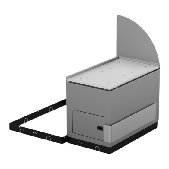
- Page 1 Kit Instructions Non-Scale 1-Bag Bagwell Upgrade 7358-K121/K125 Issue B...
- Page 2 NCR, therefore, reserves the right to change specifications without prior notice. All features, functions, and operations described herein may not be marketed by NCR in all parts of the world. In some instances, photographs are of equipment prototypes. Therefore, before using this document, consult with your NCR representative or NCR office for information that is applicable and current.
-
Page 3: Revision Record
Revision Record Issue Date Remarks Jul 2020 First Issue Nov 2021 Updated Kit Contents... - Page 5 Checkout (7358), either from a No-Bag unit or a unit with an existing Bagwell, to a unit with a Non-Scale 1-Bag Bagwell. The NCR FastLane SelfServ™ Checkout with a Bagging Area (Bagwell) Module or Large Basket (Large Basket) Module can be configured for either Left-hand (LH) orientation or Right-hand (RH) orientation, which refers to the direction customers scan and bag items.
-
Page 6: Kit Contents
7358-K121 Non-Scale 1-Bag Bagwell Upgrade (Walmart Medium Gray) on the facing page. • 7358-K125 Non-Scale 1-Bag Bagwell Upgrade (Walmart Light Blue) on page 5. Note: The 7358-K121 and 7358-K125 Kits include Core skirt panels that customers may use to replace their existing Core skirt panels. - Page 7 Non-Scale 1-Bag Bagwell Upgrade 7358-K121 Non-Scale 1-Bag Bagwell Upgrade (Walmart Medium Gray) Part Number Description 497-0528276 7358-K121 Kit - 1-Bag Bagwell Module, Non-Scale (WM Medium Gray) 795-0283428 Assembly - 1-Bag Door (WM Medium Gray) 795-0137228 Panel - Backsplash - 1-Bag (WM Medium Gray)
- Page 8 Non-Scale 1-Bag Bagwell Upgrade Part Number Description 795-0137128 Panel - 1-Bag - Front (WM Medium Gray) 795-0133328 Panel - 1/2/3 Bagwell Side (WM Medium Gray) 795-0281628 Hole Cover Label - (Light Royal Gray) 497-0528666 Assembly - 1 Bagger Frame With Leveling Feet and Casters 497-0526949 Skirt - 1-Bag BOM Package...
- Page 9 Non-Scale 1-Bag Bagwell Upgrade 7358-K125 Non-Scale 1-Bag Bagwell Upgrade (Walmart Light Blue) Part Number Description 497-0528438 7358-K125 Kit, 1-Bag Bagwell Module, Non-Scale with Lower Bagwell Bumpers (Walmart Light Blue) 795-0283412 Assembly - 1-Bag Door (Walmart Light Blue) 795-0137212 Panel - Backsplash - 1-Bag (Walmart Light Blue)
- Page 10 Non-Scale 1-Bag Bagwell Upgrade Part Number Description 795-0137112 Panel - 1-Bag - Front (Walmart Light Blue) 795-0133312 Panel - 1/2/3 Bagwell Side (Walmart Light Blue) 795-0281612 Hole Cover Label - (Walmart Light Blue) 497-0526949 Skirt - 1-Bag BOM Package 497-0464170 Assembly - 1-Bag Frame With Leveling Feet and Casters 497-0472267...
-
Page 11: Installation Procedures
Non-Scale 1-Bag Bagwell Upgrade Installation Procedures Installing the Bagwell upgrade involves the following procedures: • Installing Core Skirt Panels on the next page. Note: This procedure may be optional. • Removing Existing Bagwell on page 10. • Changing Bagwell Orientation on page 16. Note: This procedure may be optional. - Page 12 Non-Scale 1-Bag Bagwell Upgrade Installing Core Skirt Panels To install the Core skirt panels, follow these steps: Note: The 7358-K122 and 7358-K145 Kits include Core skirt panels that customers may use to replace their existing Core skirt panels. 1. On the front or back of the core, do the following: Note: The front and back skirt panels of the core must be installed before the side skirt panels of the core.
- Page 13 Non-Scale 1-Bag Bagwell Upgrade 2. On either sides of the core frame, do the following: Note: The side skirt panels of the core the must be installed after the front and back skirt panels of the core. a. Attach the skirt panel to the skirt bracket by aligning the open slots in the skirt panel with the screw holes in the skirt bracket.
- Page 14 Non-Scale 1-Bag Bagwell Upgrade Removing Existing Bagwell To remove an existing 1-Bag Bagwell, follow these steps: Note: To remove a Non-Scale 2-Bag Bagwell, refer to 7358-K122/K145 Non-Scale 2-Bag Bagwell Upgrade. To remove a Non-Scale 3-Bag Bagwell, refer to 7358-K165 Non-Scale 3- Bag Bagwell Upgrade.
- Page 15 Non-Scale 1-Bag Bagwell Upgrade 2. Remove the clear plastic deflectors from the Backsplash and side of the Core. Note: Leave the Core side deflector in its place if the new Bagwell is attached on the same side.
- Page 16 Non-Scale 1-Bag Bagwell Upgrade 3. Disconnect the following cables: • Local Area Network (LAN) Cable from the Customer Interface • AC Power Out Cables from the Power Strip • AC Power In Cable from the Power Strip Note: Remove cables from any routing clips or tie wraps if needed. 4.
- Page 17 Non-Scale 1-Bag Bagwell Upgrade 5. Remove the upper rear screw attaching the Backsplash to the Core.
- Page 18 Non-Scale 1-Bag Bagwell Upgrade 6. Remove the Bagwell by doing the following: a. Remove the two (2) bottom screws attaching the Bagwell to the Core. Screws are located on either side of power strip. b. Loosen the two (2) upper screws, but do not remove.
- Page 19 Non-Scale 1-Bag Bagwell Upgrade c. Lift Bagwell up and away from the Core Cabinet. The upper screw heads will pass through the key holes in the Bagwell side support. Note: The two (2) upper screws may be left in place if a new Bagwell will be installed in the same orientation.
- Page 20 Non-Scale 1-Bag Bagwell Upgrade Changing Bagwell Orientation To change the Bagwell orientation, follow these steps: Note: These steps should be done before attaching the Bagwell to the Core. For the purpose of illustration only, this procedure shows images using Left-hand (LH) orientation.
- Page 21 Non-Scale 1-Bag Bagwell Upgrade 2. Remove the bumpers by doing the following: Note: Do not remove the front access door bumper a. Detach the Backsplash the Bagwell by removing seven (7) screws. b. Detach the wrap-around side bumper by removing three (3) flat head screws and spacers, as shown in the image below.
- Page 22 Non-Scale 1-Bag Bagwell Upgrade 3. Remove two (2) nuts securing the front panel to the Bagwell frame located at the inside corner posts. 4. Pull down the front panel and then pull out to disengage from the slots in the Bagwell frame base, as shown in the image below.
- Page 23 Non-Scale 1-Bag Bagwell Upgrade 5. Install the front panel on the opposite side of the Bagwell and secure it with two (2) nuts. Note: Ensure that the the lower hook features are properly aligned with the slots in the Bagwell frame base. 6.
- Page 24 Non-Scale 1-Bag Bagwell Upgrade Installing New Bagwell To install the new Bagwell, follow these steps: Note: If changing the Bagwell orientation (Left-Hand or Right-Hand), ensure that the orientation is changed before installing the new Bagwell to the Core. For the purpose of illustration only, this procedure shows images using a Left-hand (LH) orientation unit.
- Page 25 Non-Scale 1-Bag Bagwell Upgrade 3. Lower all the leveling feet of the Bagwell slightly beyond the height of the casters to assist in lining up the Core and the Bagwell mounting holes. 4. Install the new Backsplash panel using seven (7) screws.
- Page 26 Non-Scale 1-Bag Bagwell Upgrade 5. If not already present, partially thread the two (2) upper screws on the Bagwell side of the Core. Leave approximately ¼ inch of the threads exposed. 6. Mate the new Bagwell to the Core by lifting the frame up and over the partially threaded screws.
- Page 27 Non-Scale 1-Bag Bagwell Upgrade 7. Tighten the two (2) screws and install the two (2) lower screws that connect the Bagwell and the Core. 8. Install the upper rear screw attaching the Backsplash panel to the Core. Note: Adjust the leveling feet if the slot does not line up well.
- Page 28 Non-Scale 1-Bag Bagwell Upgrade 9. Route the following cables through the cable access hole: Bagwell Cable Access Hole • AC Power In Cable Core Cable Access Hole • Local Area Network (LAN) Cable • AC Power Out Cables For more information, refer to Routing Cables on page 28.
- Page 29 12. Attach the Bagwell Skirt Panels. For more information, refer to Installing Bagwell Skirt Panels on the next page. 13. Level the unit and attach the bag racks, if necessary. For more information, refer to the NCR Fastlane SelfServ™ Checkout (7358) Hardware Installation Guide (B005– 0000–5263).
- Page 30 Non-Scale 1-Bag Bagwell Upgrade Installing Bagwell Skirt Panels To install Bagwell skirt panels, follow these steps: 1. On the side of the Bagwell, do the following: a. Attach the skirt panel to the skirt brackets by aligning the open slots in the skirt panel with the screw holes in the skirt bracket.
- Page 31 Non-Scale 1-Bag Bagwell Upgrade 2. On the front and back of the Bagwell, do the following: Note: The front and back skirt panels of the Bagwell must be installed after the side skirt panel of the Bagwell. a. Attach the front and back skirt panels to the skirt brackets by aligning the open slots of both skirt panels with the screw holes in the skirt bracket.
-
Page 32: Routing Cables
Non-Scale 1-Bag Bagwell Upgrade Routing Cables To route cables when installing a new Bagwell, follow these steps: Note: If a new Bagwell is installed to a No-Bag unit, refer to Routing Cables for No-Bag unit on page 30. 1. Route the Local Access Network (LAN) Cable from the Core to the Customer Interface through the smaller opening of the Bagwell frame, as shown in the image below. - Page 33 Non-Scale 1-Bag Bagwell Upgrade 2. Route the AC Power Out and AC Power In cables and then connect to the Power Strip, as shown in the image below.
- Page 34 Non-Scale 1-Bag Bagwell Upgrade Routing Cables for No-Bag unit These are additional steps in routing cables when upgrading a No-Bag unit to a 1-Bag unit: 1. Detach the rear Core panel by removing six (6) screws to access the main cable bundle and Power Strip.
- Page 35 Non-Scale 1-Bag Bagwell Upgrade 2. Unplug the AC Power Out and AC Power In cables from the Power Strip. AC Power In Cable will be reused in the new Bagwell. AC Power Out Cable should be routed either through the left-hand or right-hand lower Core access cutout into the new Bagwell.
Need help?
Do you have a question about the 7358-K121 and is the answer not in the manual?
Questions and answers